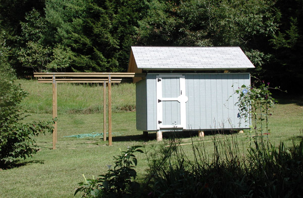
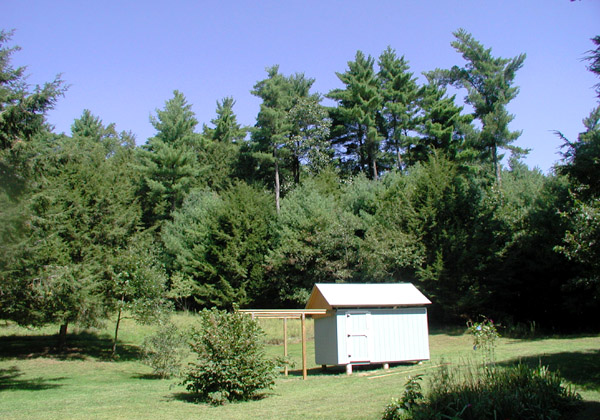
Introduction: This page will document the construction of my backyard observatory. This is a project I had wanted to do since the summer of 1975. A variety of factors (mainly lack of cash and a suitable location) caused the 30+ year delay in starting this project. I live in a place where (for southern New England anyway) the skies are still reasonably dark and I expect to be here long enough to make construction of an observatory a worthwhile undertaking. The photos below document the progress of observatory construction.
The observatory I built is a roll-off roof type observatory, I decided on dimensions of 8x12. I did not have a set of plans, I kind of just "made things up as I went" (but I had a pretty good idea of what I wanted to do after doing some basic research and looking at other designs). My budget for this project was around $2500, so that means I am doing nearly all the labor myself. I did purchase most of the construction materials right after the Katrina disaster, mainly to beat the significant increases in material prices caused by this and other storms. Plywood went from $25 a sheet to $31 a sheet in 4 days (I had to make multiple trips on multiple days due to the capacity limitations of my truck).
Important: Although this page shows quite a bit of detail, this page is not intended to be a "step by step how to" page on building an observatory. If you decide to undertake such a project, be certain to follow local codes and laws. Such policies vary considerably depending on where you live, and there may be other considerations (earthquake proof, snow loading, etc) that you may need to adhere to. You will need to be familair with and comfortable using basic tools (both hand tools and power tools) to complete a project like that shown below. If you are not 100% sure you are qualified to do part or all of the job, hire a qualified professional.
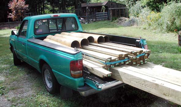
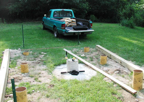
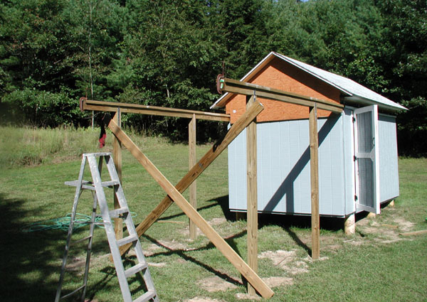
18 September 2005: one of several pickup truck loads of materials. All framing materials for this observatory will be pressure treated. I do not ever want to have to deal with termite or ant damage. I purchased about eighty 2x4 studs (will probably need a few more however). The main beams for the foundation will be 6x6 pressure treated beams. Doing everything in pressure treated wood cost somewhat more, but I'd rather pay somewhat more now as compared to having to do major repairs at some point in time.
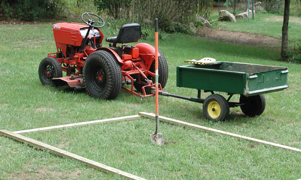
18 September 2005: Groundbreaking! This is the start of the hole for the telescope pier. The dirt, rocks and sand removed for the pier hole were used to fill sinkholes in other parts of the yard. The 2x4 boards on the ground represent the rough outline of the building footprint.
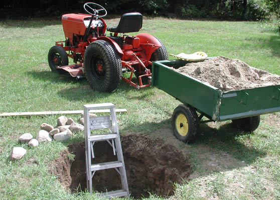
After several hours of digging (maybe 7 or 8 wagonloads), the hole is finished. It is just under 5 feet deep and about 3.5 feet diameter. A stepladder was needed to get into and out of the hole conveniently.
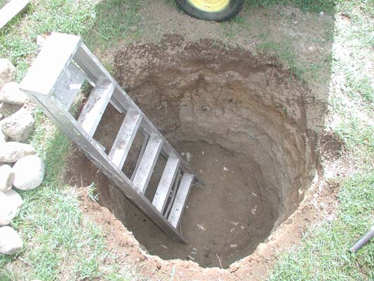
Another view of the pier hole.
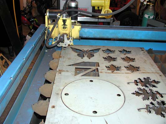
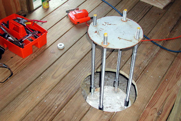
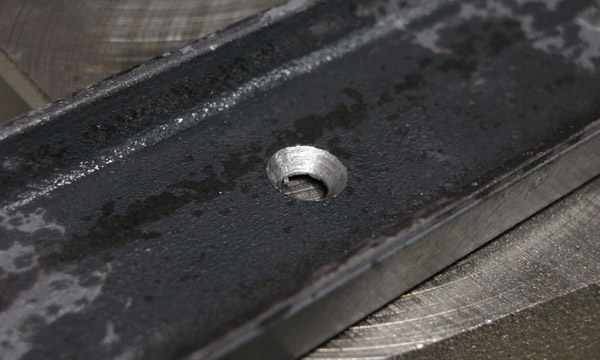
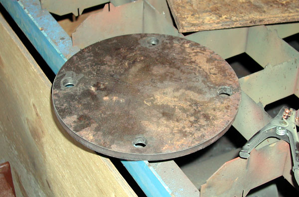
24 September 2005: Cutting of a stud alignment plate using my brother's Plasma Cam machine. This plate (round piece with 4 holes in it, made of 1/8" thick steel) will be used to align the threaded rods when they are set into the concrete pier. The telescope pier will eventually bolt up to the threaded rod.
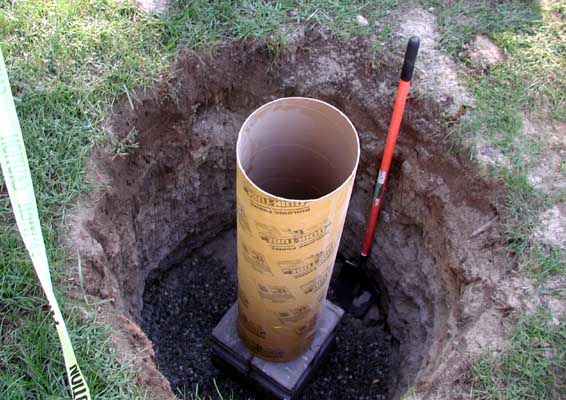
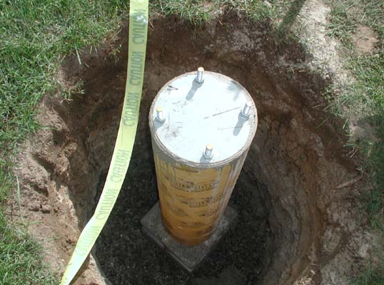
25 September 2005: a view of the 12" sonotube sitting in the pier hole. The tube has been leveled and is sitting on 4 concrete blocks.
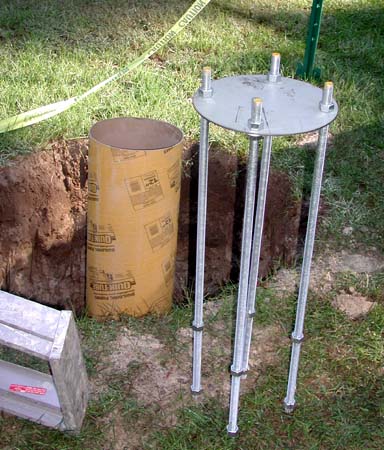
A view of the 3/4" threaded rod and the stud alignment plate. This assembly will be inserted into the 12" sonotube after it is filled with concrete. The plate assures that the (yet to be made) steel telescope pier will exactly fit over the threaded rods. The threaded rod extends a little less than 3" above the plate.
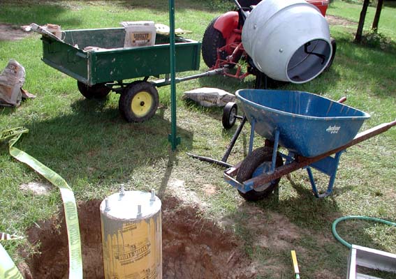
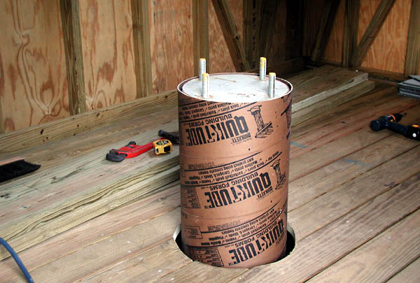
25 September 2005: The sonotube has been filled with concrete and the threaded rod assembly has been placed into the concrete (in addition there are 5 pieces of rebar in the tube). The studs are lined up to north/south to within a degree or so (this will allow easier polar alignment when the time comes). For this job, I mixed the concrete myself (takes about 5.5 bags 80 pound bags to fill a 4 foot tall 12" diameter sonotube).
Another view of the telescope pier just after the concrete pour.
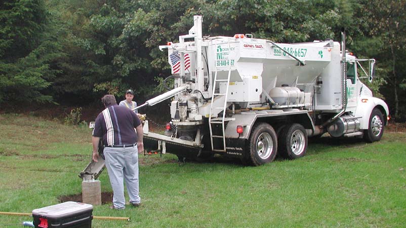
8 October 2005: More concrete pouring. Today, the rest of the pier hole was to be filled with concrete (the sonotube cardboard was first removed from the first pour). For this job, I hired a concrete outfit (McKinney Mobile Mix) to do the job. I needed about 1.75 yards of concrete: to get this amount from Home Depot would have taken at least 7 trips in my truck (at about 25 miles per trip), and then I would have had to mix and pour it all myself! A potentially huge, dirty job. The total cost of the concrete from McKinney Mobile Mix (including delivery, mixing and pouring) was about 10 percent LESS than just the cost of the concrete I would have had to buy from Home Depot (about seventy eight 80 pound bags)! For this amount of concrete, it made no sense to do the work myself. This is one of the trucks that mixes what you need on the spot, you only pay for what you need. Although today was a rainy day, it did not matter for the job I was having done (the concrete was going into a big hole in the ground).
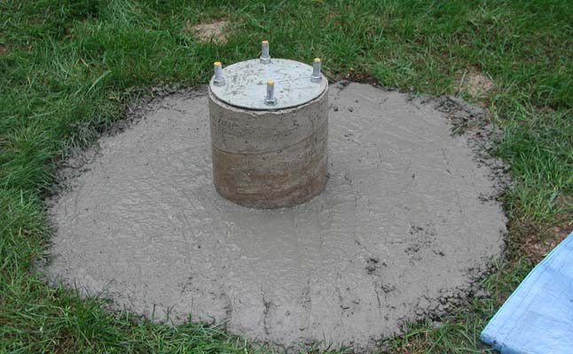
A view of the final concrete pour on the pier. The total weight of the pier is about 7200 pounds. It won't be going anywhere anytime soon!. The design is such that the pier will be independent of the main observatory building foundation, so no vibration from walking around will be transmitted to the telescope (a critical factor for photo imaging). This activity pretty much finished up activity for 2005. Due to my hectic schedule there would be no way I could fabricate the building before the winter season arrived.
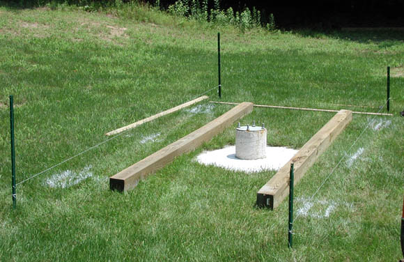
1 July 2006: Finally, after one of the wettest spring seasons on record, work can begin again! This photo shows the process of laying out where the sonotubes will go (sonotubes will support the main beams for the frame of the observatory). I used a can of white spray paint to mark on the ground where the holes needed to be dug.
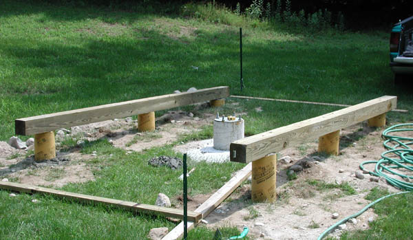
All holes dug (not without major effort), tubes in place and leveled. The holes for the sonotubes did not exactly line up as I wanted to. There are so many rocks that it is one step away from being impossible to use a post hole digger around here. Rocks the size of grapefruits and cantaloupes were causing major headaches and lots of hand digging. Despite the tubes not all lining up exactly, the purpose will be met. The main pier is offset slightly: it is a little west of center (to allow room at one end of the observatory for a computer bench) and also a little south of center (most of the time will be spent on the north side of the scope).
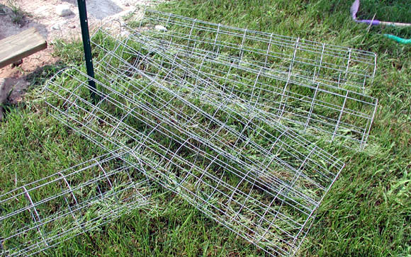
I made up some Wire cages (basically galvanized fence wire) to reinforce the concrete that will be poured into the sonotubes.
July 2 2006. Preparing to mix and pour concrete into the sonotubes. I did not have the concrete mixer today, so unfortunately all of the concrete had to be mixed by hand (a lot of work). The wire reinforcement cages were placed into the tubes prior to filling with concrete. Also (not shown), the 6x6 beams have been drilled to accept 5/8" threaded rod.
A view after the concrete has been mixed and poured. A 2 foot long piece of 5/8" threaded rod was placed into each sonotube (down through the holes that were drilled in the 6x6 beams). These will serve to anchor the observatory building to the pilings. In my area this is not a code requirement (for a building of this size), but I prefer to do it this way.
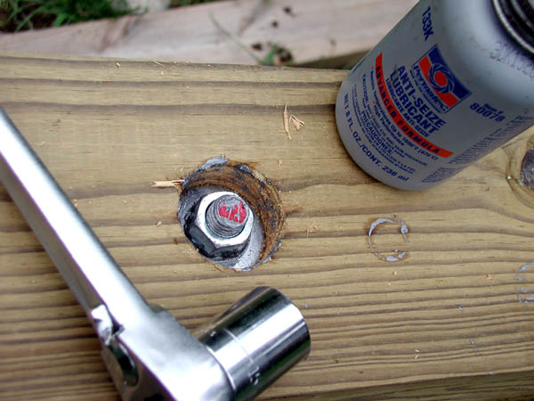
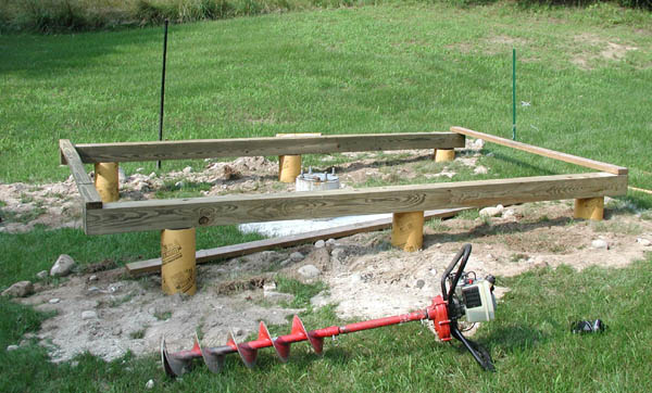
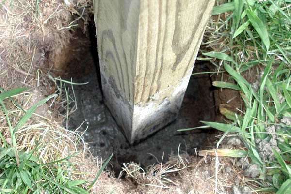
Securing the 6x6 beams to the sonotubes. 5/8" threaded rod goes down about 20" into the concrete, the beam is secured with a washer and nut. I don't ever expect to have to take the nuts off, but in case I have to Anti-Seize was used to keep them from jamming up.
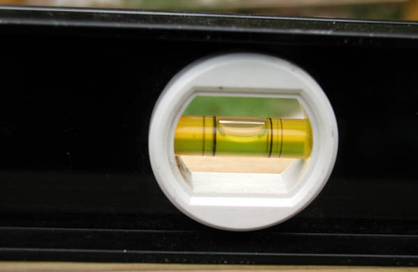
Pretty level... not perfect, but good enough for me.
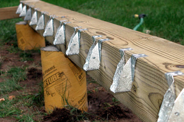
A view of the floor beam hangars in place on one of the 6x6 beams. Normally 2x4s are not used for floor beams, however I had a large number of them available. They are spaced on 12" centers to make up for not being 2x6 beams.
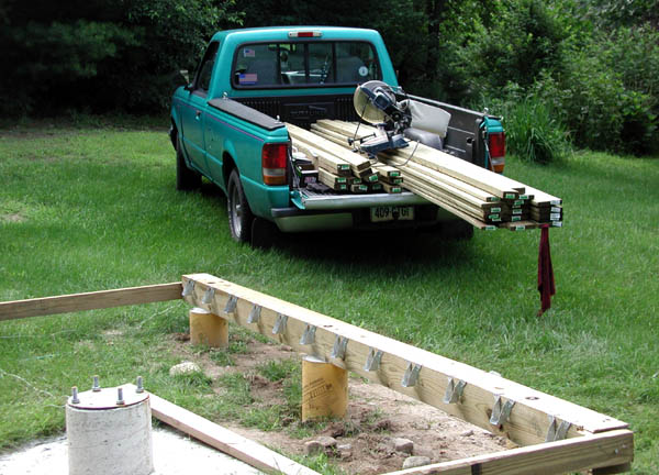
8 July 2006. A load of material for floor beams and floor planks (actually deck planks). Various tools (including a chop saw) are also on the truck.
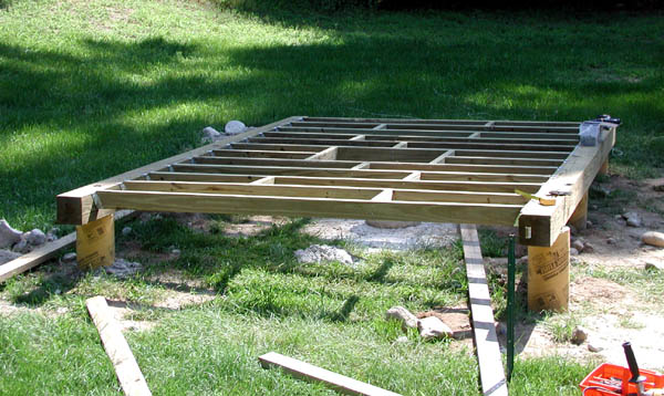
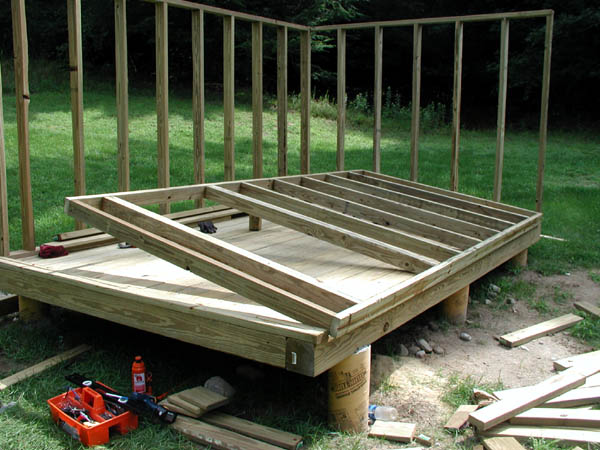
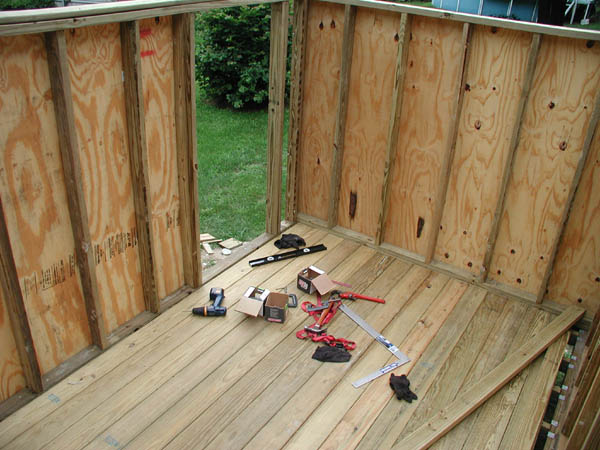
8 July 2006: Today was spent framing up the floor, the final result is shown above.
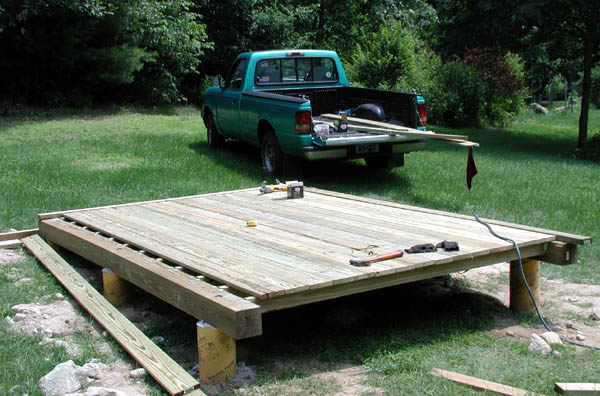
Next, the deck boards were installed (all but one plank that has to be ripped the whole length, this was added later). Over 360 deck screws had to be put in (a pain in the back). The hole for the pier will be cut later (if I cut it now for sure I will fall into it during other work)!
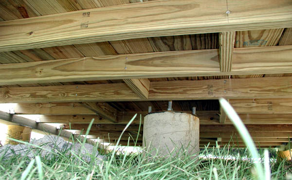
A view from underneath the floor (pier is visible at center).
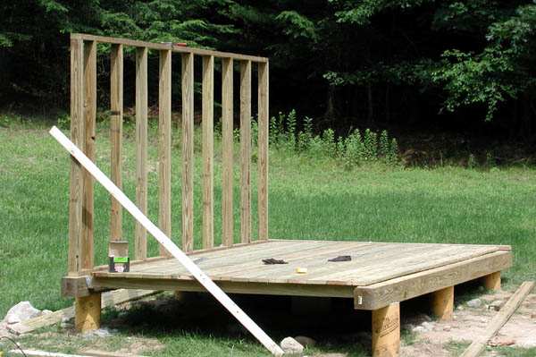
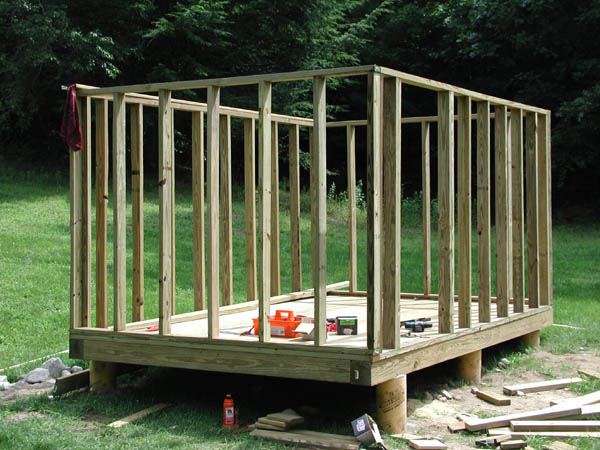
Next up is the north wall frame. Here is a view (with a temporary support) of the result.
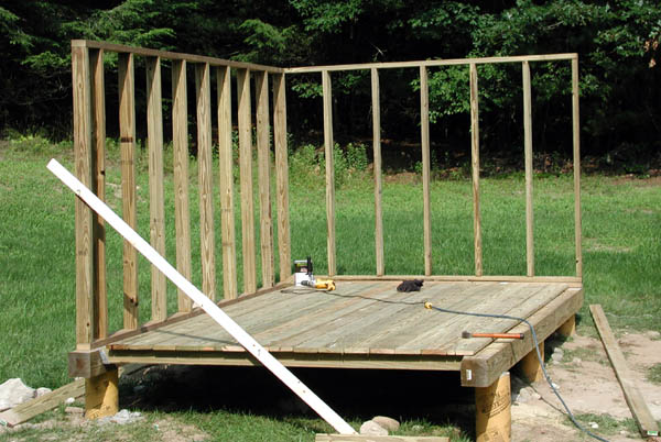
The east wall framing was added next. That pretty much wraps the work for the day (8 July 2006).
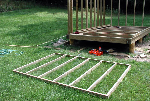
15 July 2006: The west wall framed and ready for installation (I pre-fabricated this frame section in the garage during the week).
15 July 2006: The south wall framed up and ready to be installed. I cut all the pieces for this framing during the week but assembled it on site (it would be too heavy and bulky for me to [easily] carry alone). The door is 32 inches wide and just under 6 feet tall.
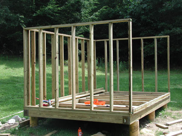
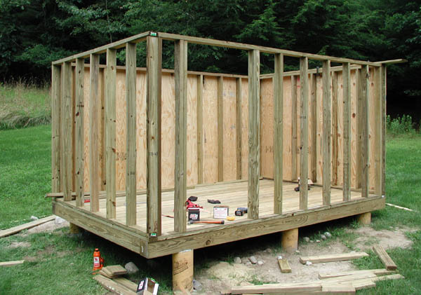
15 July 2006: West wall frame after installation.
15 July 2006: South wall frame after installation.
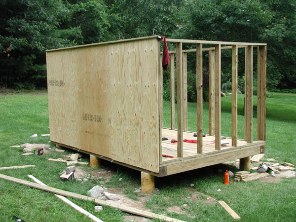
15 July 2006: North wall with plywood installed. This is 3/4" plywood and was a royal pain to install by myself (it is heavy and bulky, trying to hold it in place and nail it was a pain, lots of swearing!). I finally had to improvise a method to hold them (nails pounded into the 6x6) in order to do the job efficiently.
15 July 2006: East wall plywood is now up.
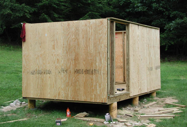
15 July 2006: West and south walls (all but one small piece of plywood for the south wall) with plywood installed.
15 July 2006: A view from the inside northeast corner of the observatory (looking southeast). Today was VERY hot. Due to the swarm of deerflies around here (very aggressive and extremely annoying pests) I had to wear long pants, sweatshirt, bug net, gloves and hat. It felt very good to take a dip in the pool after all this work! Next major task: roller planks for the roof!.
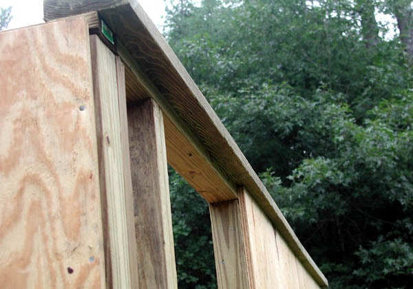
22 July 2006. A 4x6 beam installed on top of the south wall. This is the beam that will support a steel track (the roof rollers will ride in the track).
22 July 2006. Another view of the same beam as seen from the inside of the observatory.
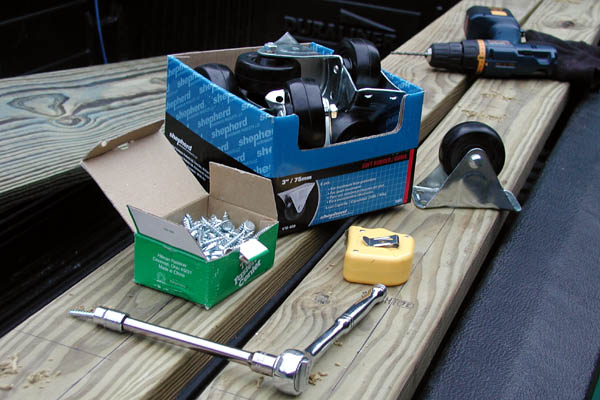
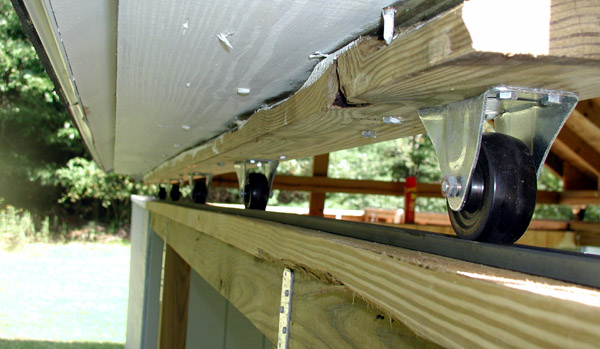
22 July 2006. Preparations for installing the rollers on 4x6 beams. I used ten 3" casters, each rated at 225 pounds. They will be spaced at approximately 28 inch intervals and installed with four 1.5" lag bolts each.
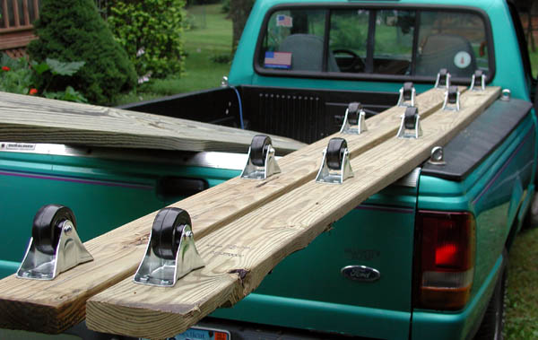
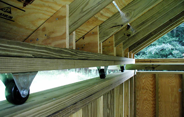
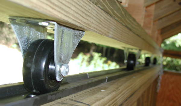
22 July 2006. A view of the two beams with rollers installed.
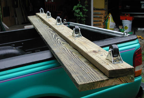
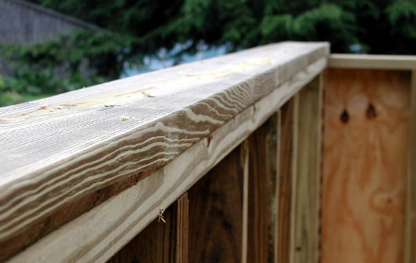
22 July 2006. The 4x6 beam with rollers has been lag bolted to a 2x12 beam (12 feet long). This assembly was HEAVY (~90 pounds)... the 2x12 pressure treated plank was the bulk of the weight. These 2x12 PT planks are not cheap, like $22 each!.
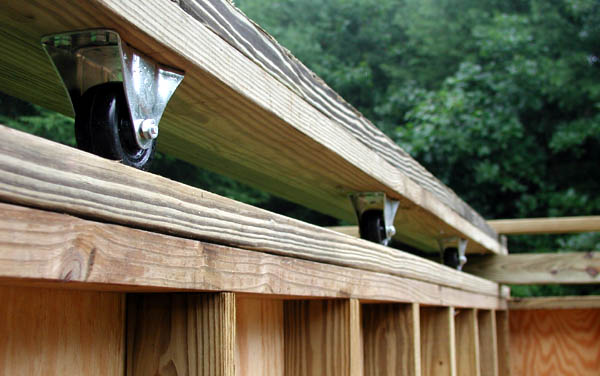
22 July 2006. A view showing the roller planks sitting on the top of the walls. I used two 4x4 beams (12 feet long) perpendicular to these in order to prevent them from falling off while construction continues. I secured the roller planks in place temporarily using two 2x4 x 12 foot boards These roller planks must remain exactly parallel during further construction. From outside edge to outside edge the measurement is 114 inches. The steel track (that will rollers will ride in) will be installed later.
22 July 2006. A view of the south wall (from the inside of the observatory) showing the roller plank. The 4x4 beam can be seen near the back wall, this prevents the roof assembly from sliding off during further construction.

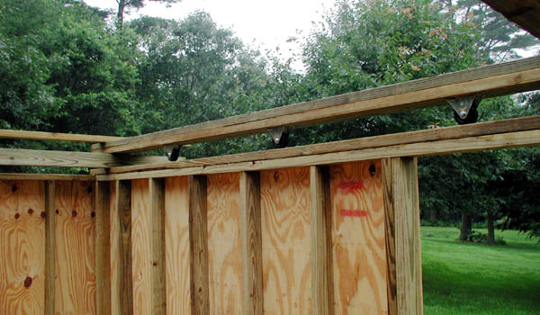
22 July 2006. An outside view showing the installation of roller planks. The 2x4 x 12 foot boards can be seen (these hold the two roller planks true to each other) and the 4x4 x 12 foot beams can also be seen (these prevent the roller planks from falling off the structure while additional construction continues). Next major task: fabrication of roof trusses!
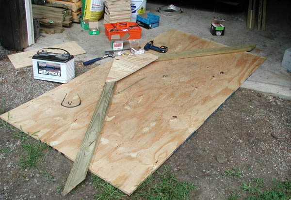
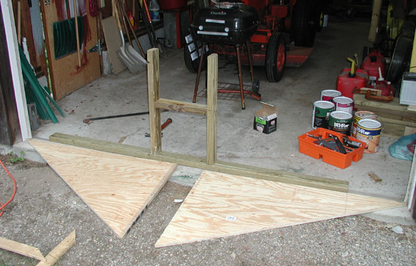
26 July 2006. Ideally roof trusses need to be all the same shape. To assist with fabrication of the trusses, I used a piece of plywood to mark out a template to allow easy alignment of the roof trusses. The first truss is shown here. Note the gusset used at the apex of the truss. Each was secured with multiple lag bolts and nails.
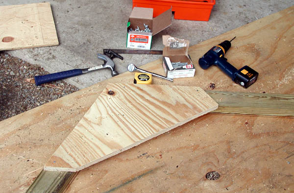
26 July 2006. Close up of the gusset. The shape one this one is a bit irregular as I was trying to maximize use of scrap plywood. Many of the gussets were full triangles. These were installed with nails and 6 lag bolts.
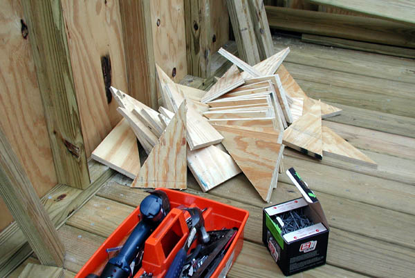
26 July 2006. I cut a large pile of additional roof gussets. These will be used to strengthen the joint between the roof trusses and the roller planks.
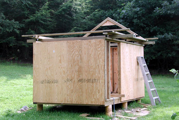
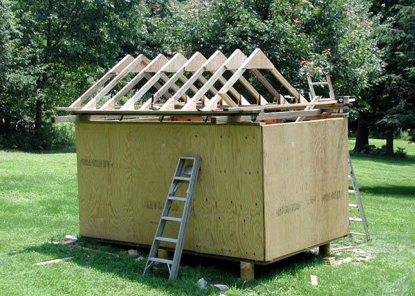
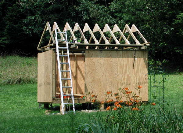
26 July 2006. A view of most of the roof trusses awaiting installation, resting on the roller planks. One has already been installed (in the back on the end of the roof).
26 July 2006. One roof truss installed on the east end of the roof.
26 July 2006. Several more roof trusses installed.
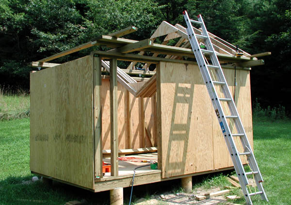
26 July 2006. Another view of roof trusses being installed.
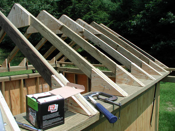
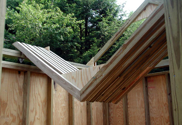
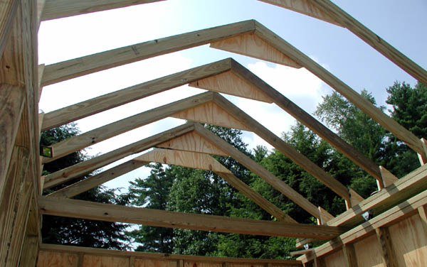
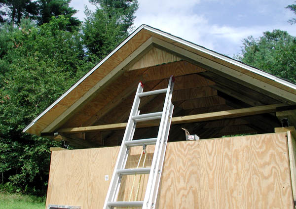
26 July 2006. A view from the ladder. Note how the trusses are installed relative to the roller planks. The gussets will greatly increase the ability of the roof to withstand snow loads.
26 July 2006. Several more trusses installed.
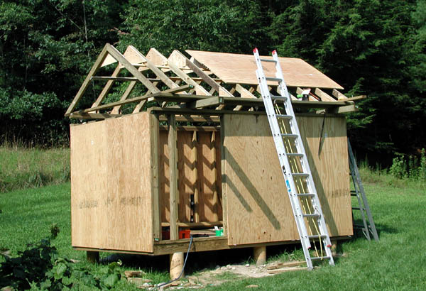
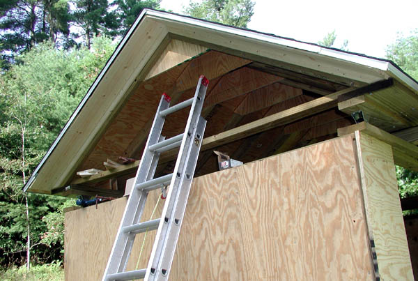
26 July 2006. A view with most of the roof trusses now in place.
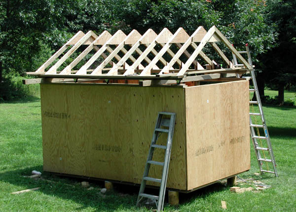
26 July 2006. All roof trusses now in place.
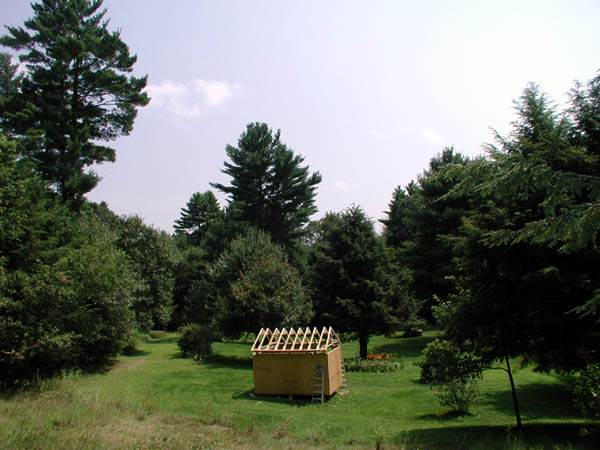
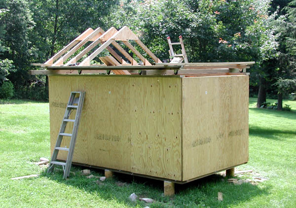
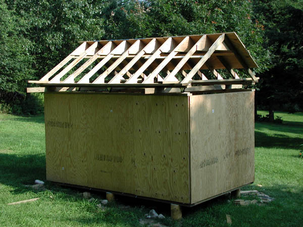
26 July 2006. A view from the hill, looking slightly east of south.
26 July 2006. A view looking north. Note a few trusses are not true (due to some 2x4 boards being warped, this is taken care of in the next photo.
26 July 2006. The first piece of plywood installed on the roof. This is 3/4" plywood and is HEAVY and difficult to get up to the roof working alone! I had to improvise a method to work it up to the roof while standing partly on the ladder. Note the addition of temporary 1x3 furring to the inside of the trusses, this was added to hold all trusses true before installation of plywood. A few of the trusses were made with warped 2x4s, one of them needed some persuasion (using a pipe wrench) to force it true. The temporary 1x3 boards will be removed once all the plywood is in place.
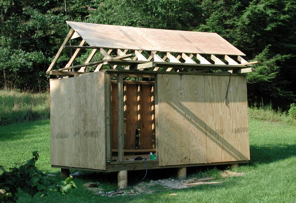
26 July 2006. One more plywood section added.
26 July 2006. A view looking southeast. That wraps up a full day of work (7am to 5:30pm). Another steamy day, temp was over 90 with high humidity... time for a dip in the pool!
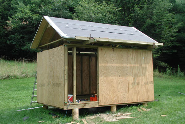
30 July 2006: A view with all the roof plywood work completed. Note that with the method I used the plywood seams do not all land on joists. This is not an issue as I used additional scrap plywood sections (secured to the inside seams using dozens of screws) to strengthen the joints.
30 July 2006: A view of the rollers on the north side of the observatory along with the gussets and roof structure.
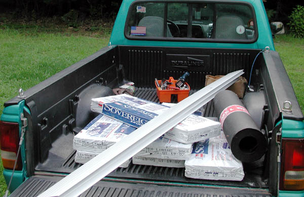
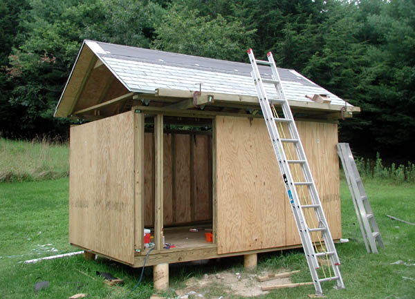
1 August 2006: Roofing day! Unfortunately, today is forecast to be one of the hottest days of the heat wave, air temp approaching 100 with heat index of 105-110 degrees! Here is a load of material for the day's work. Hot or not, this work has to get done.
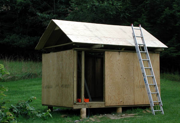
1 August 2006: A view that shows the completed installation of roofing paper and drip edge. The 4x4 beam at the edge of the roof serves 2 purposes: first, it keeps the ladder away from the drip edge and shingles and second it will act as a guard to keep me from sliding off the roof. The pitch on this roof is just enough to not be able to casually walk around on it.
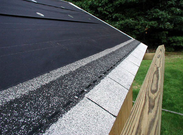
1 August 2006: A starter course of shingles.
21 August 2006: The south side about 1/2 done. This job went VERY slow due to a problem with the shingles. Each shingle has a backing that has to be peeled off, and the backing was not ripping smoothly on many of the shingles. I am not sure if it was a bad lot or what (some of them were fine). It was being a royal pain as the backing would rip erratically and it required that the backing be taken off in small chunks. Wish I had a dollar for every swear spoken on this day! This is a 200 square foot roof and it took me ALL DAY to complete it! This kind of a job should have gone a lot faster...
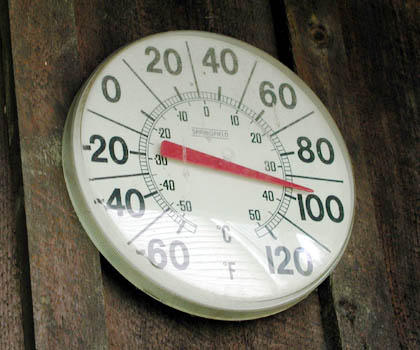
1 August 2006: The "shade" temperature at around 2pm. It was VERY hot working on the roof today. Due to extremely aggressive deerflies, I was dressed in long pants, sweatshirt, hat and bug net... very hot but better than being bitten dozens of times. I was so wet from sweat it was as if I had jumped in the pool fully clothed... and in fact I did just that several times! Even though the shingles were a light color, the roof was so hot it was barely possible to touch it. My wet clothes helped to cool things down a bit. I drank 16 bottles of water during this roofing activity. I also had a garden hose and wet myself down at least a dozen times. Not a great day for roofing, but this work had to be done as this was my day off.
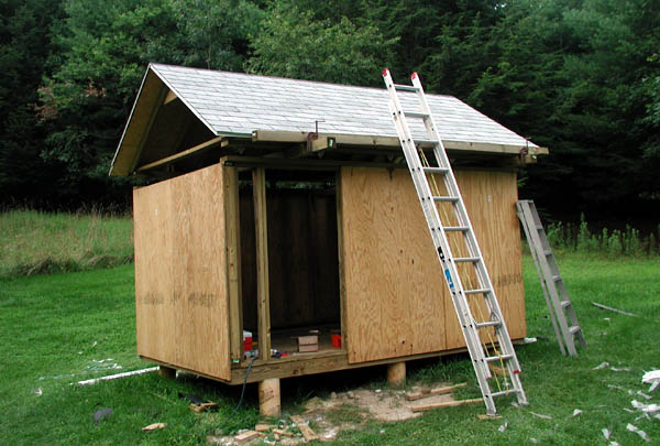
1 August 2006: Finally! The shingle job is complete except for the ridge shingles (this is lower priority and will be done later). The inside of the structure is now protected from rain!
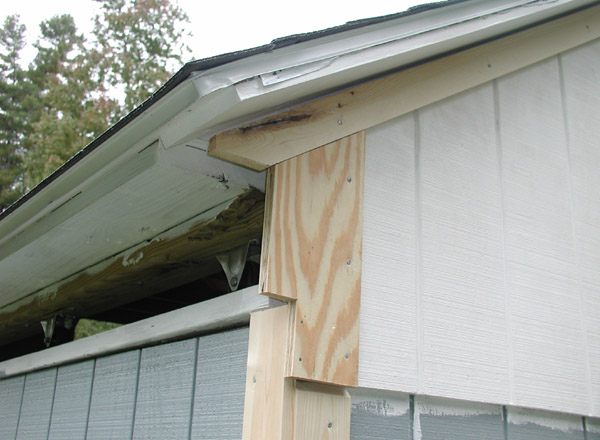
4 August 2006: Time to work on the west end of the roof; this part of the roof will move with the roof (the other end will stay put, more on that later). To allow proper overlap of siding, some 1x3 spacers have been added on top of the 2x4 end trusses.
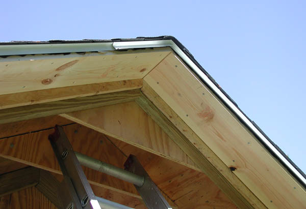
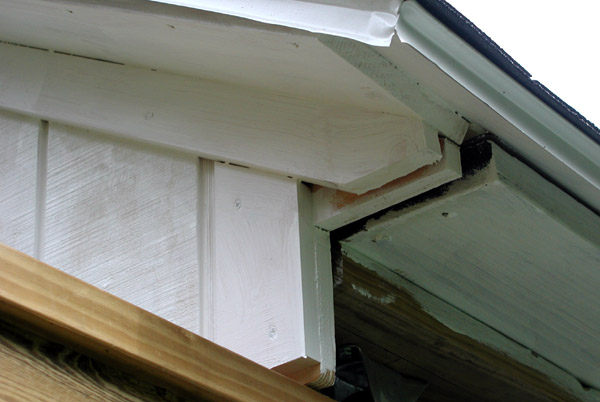
4 August 2006: Addition of some 1x8 pine boards under the eaves. The reason for this will become obvious later on (too hard to explain now, will show in photos later on why this needs to be done).
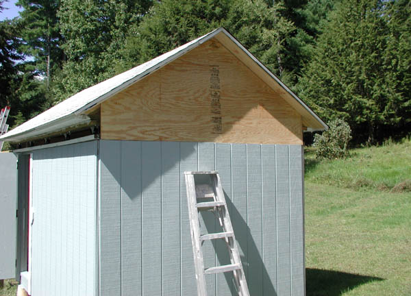
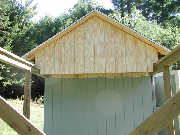
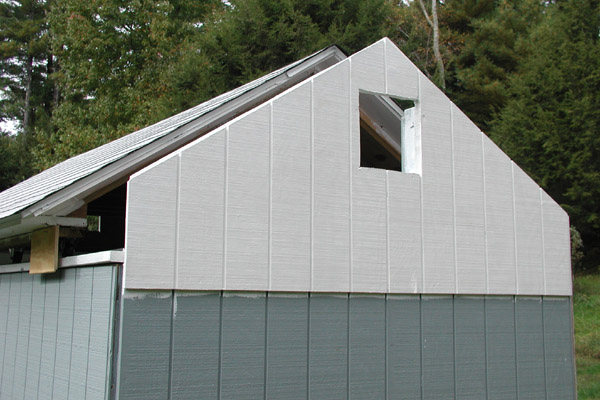
4 August 2006: Addition of the end panel at the west end of the observatory. This was a royal pain to do alone, had to more improvising to get this section in place, level and nailed in. The roof will move off to the west (on a yet to be built track), note how this upper section overlaps the lower section. This is not the final siding for this observatory, I have not decided on the type of siding at this time (T-111, cedar shakes, boards, etc).
4 August 2006: Another view of the day's work. I also added in the small plywood section to the west of the door opening. Later on at night when it got dark, I used a laser level to mark out the lines for where the track supports will go. The track for the roof is probably the major task remaining, I will need to dig 4 holes and install four 4x4 upright beams to support the roll off track.
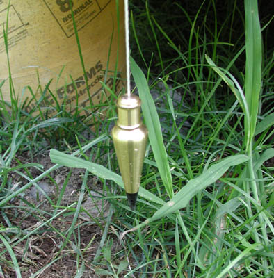
5 August 2006: A plumb bob is used to determine the point on the ground that is exactly centered on the beam that will hold the tracks for the rollers.
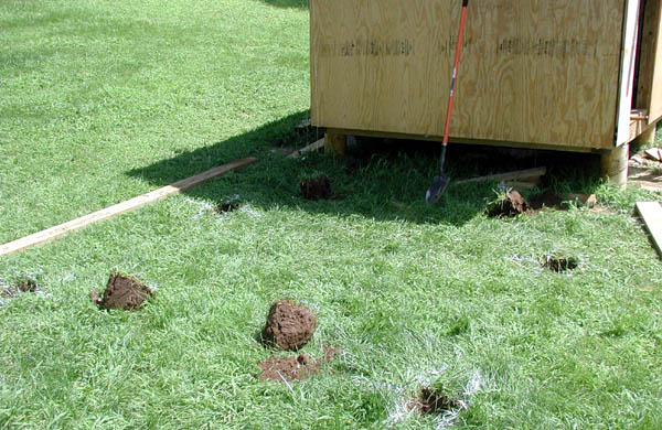
5 August 2006: Starting the holes for the tracks supports.
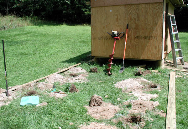
5 August 2006: After a staggering amount of work (due to rocks), the 4 holes are dug. I wish I had a dollar for every rock I hit. Some were the size of cantaloupes!
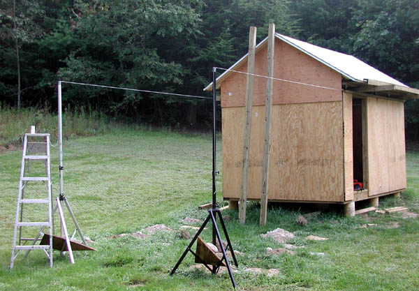
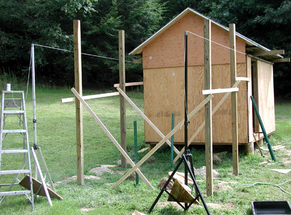
19 August 2006: Here I am preparing to line up the track supports. I am using some old DJ equipment (lighting stands) to hold some mason line. Basically I made the mason line exactly true with the main beams on the observatory. The string will act as a guide so I know exactly where to place the track support poles (4x4 pressure treated beams).
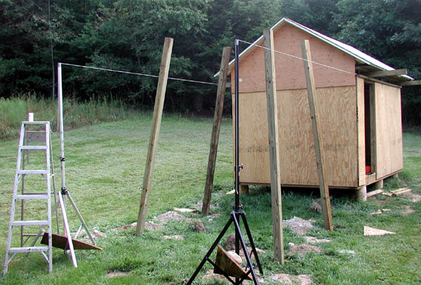
19 August 2006: The 4x4 track supports are placed loosely in their holes. They are 12 feet long. Due to the number of rocks, the best I could do for depth of the holes was about 30-33 inches.
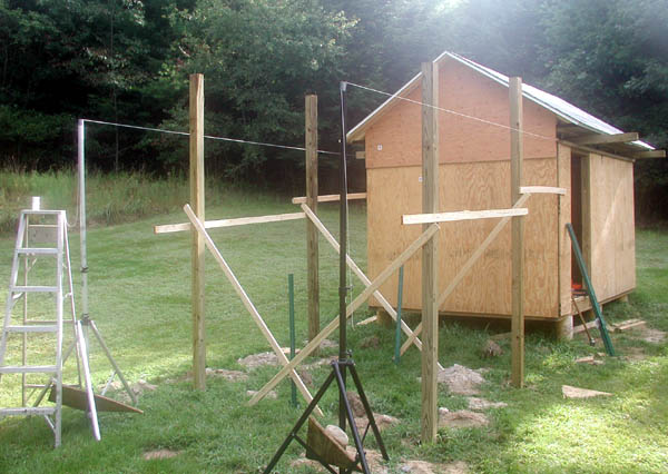
19 August 2006: All of the track support poles have been made true, I used some 1x3 furring strip wood to hold them all true. Next, concrete will be poured into the holes around the uprights.
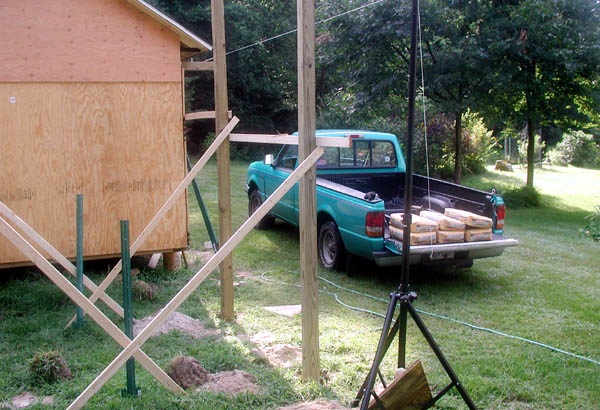
19 August 2006: Preparing for more concrete mixing.
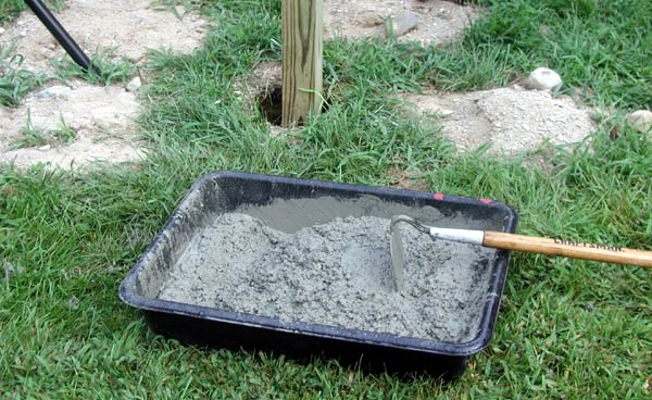
19 August 2006: One 80 pound bag of ready-mix all set to pour into the holes. I used 1.5 bags per hole.
19 August 2006: Concrete poured into the hole. I purposely did not fill them all the way to the ground surface. I kept the concrete level about 8-10 inches below the surface of the ground so that winter freezing would not cause the poles to heave up. I have heard people say the frost line is several feet around here... however I have had to dig before in the dead of winter and have never seen the frozen layer more than about 6 inches thick.
19 August 2006: All four track support poles with concrete poured. Next they will be cut to proper length.
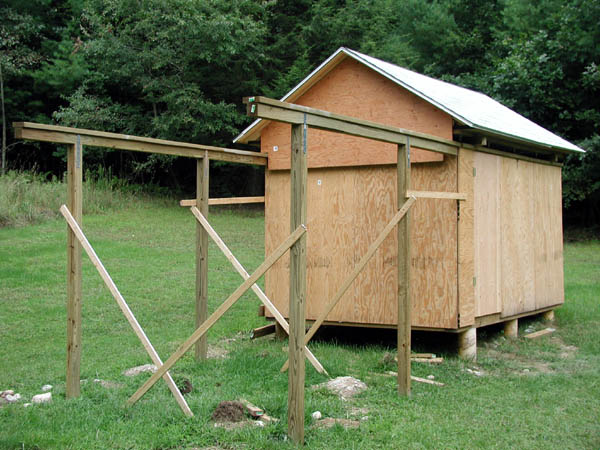
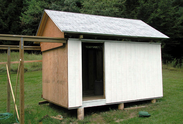
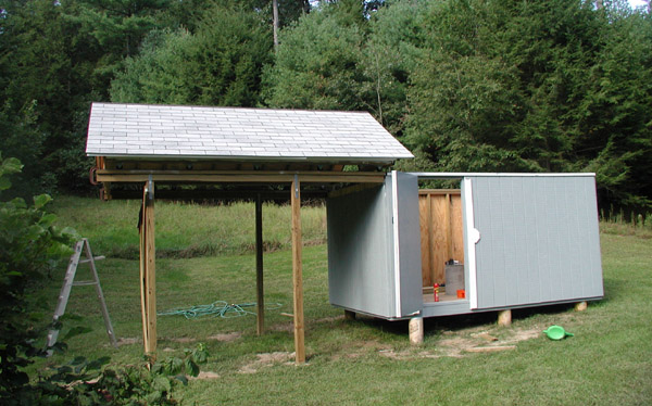
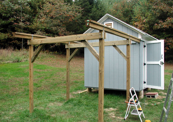
30 August 2006: A view of the track support poles cut to proper length and also the horizontal 4x4 beams have been added. been added. A 2x6 board sits on top of each 4x4, and the steel track will be placed on top of this eventually. Also, a preliminary door has been installed temporarily. The 4x4 beams used for the horizontal track supports were the ones used to hold the roof in place; I used some other smaller wood scraps to keep the roof from moving as I did not feel like buying 2 more 4x4x12 foot beams.
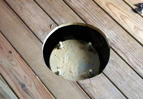
30 August 2006: The hole in the observatory floor has been cut to reveal the pier. Originally I was going to have the steel pier bolt right to this, however I later decided to extend the concrete pier.
30 August 2006: Preparing to extend the pier: 3/4 inch diameter threaded rod has been coupled to the existing studs using threaded rod couplers. The stud alignment plate (made last year) is used once again to hold the rod true.
30 August 2006: A 12 inch sonotube section is placed over the existing pier, also inside is wire reinforcement for the concrete. I poured the concrete for this (3 bags) on the evening of 01 September.
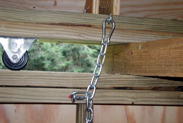
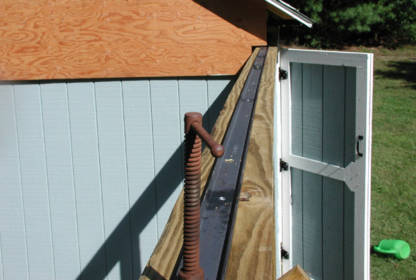
02 Sep 2006: The remnants of Tropical Storm Ernesto were predicted to possibly hit our area, so I expedited the roof securing mechanism. The roof probably weighs over 1000 pounds, but wind can be very powerful and I wanted to take no chances. These chains and quick release clips ensure that the roof will not be moved by a large gust of wind. They will also be used to secure the roof during "normal" operation.
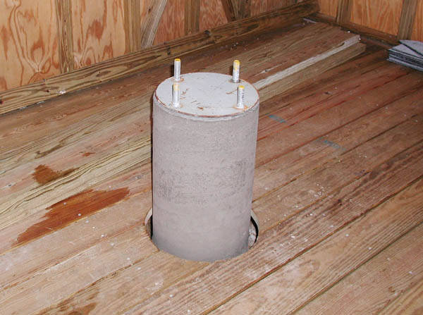
04 Sep 2006: The concrete pier extension after pouring and with the cardboard removed. This pier extends to about 18 inches above the floor. The rest of the pier (yet to be fabricated) will be steel. I did not want the concrete part too tall in case I ever decide to install a large Newtonian scope (a fat pier could interfere with the tube motions).
04 Sep 2006: Addition of siding. This photo shows T-111 siding installed on the south wall and also a coat of primer.
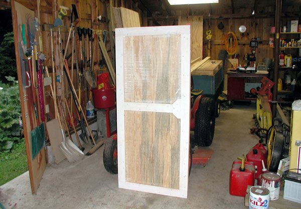
04 Sep 2006: Door fabrication. The preliminary door has been beefed up. The door is 3/4 inch plywood and 5/8 inch T-111 and 1x4 pine trim (all put together with glue and screws. It is very strong and quite heavy.
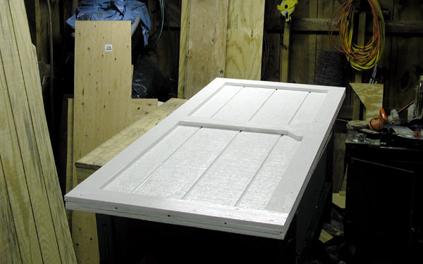
04 Sep 2006: The door with primer applied. Note the thickness of the door!
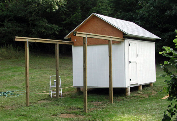
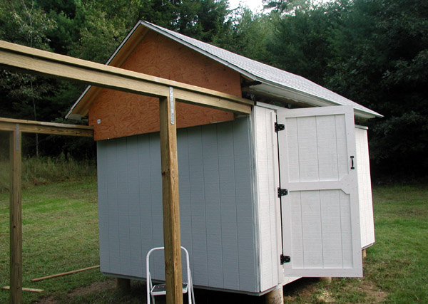
08 Sep 2006: T-111 siding has been installed all the way around and primer has been applied. It took about 3 gallons of primer to do the siding, the T-111 is rough and really takes a good coat to cover it. Also, all the support wood from the track support poles has been removed.
08 Sep 2006: Another view, note the upgraded door is installed (it is not done completely but it is a lot farther along).
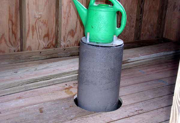
08 Sep 2006: Keeping the concrete pier wet. Concrete does not "dry" like paint, it is a chemical reaction and will cure for weeks. It is best to keep it wet for proper curing, I wet it down 2 or 3 times a day for about 2 weeks.
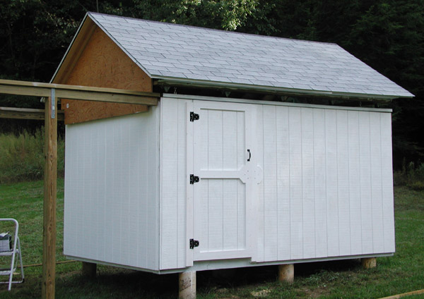
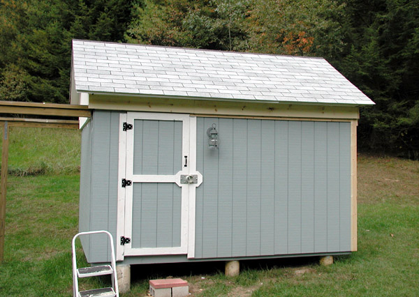
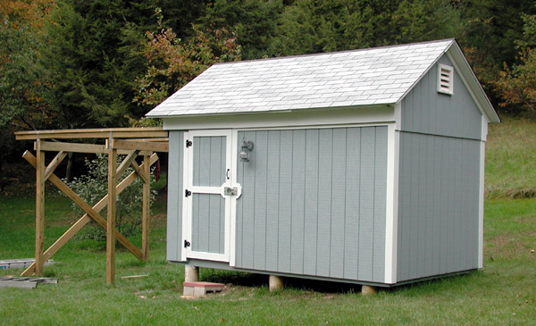
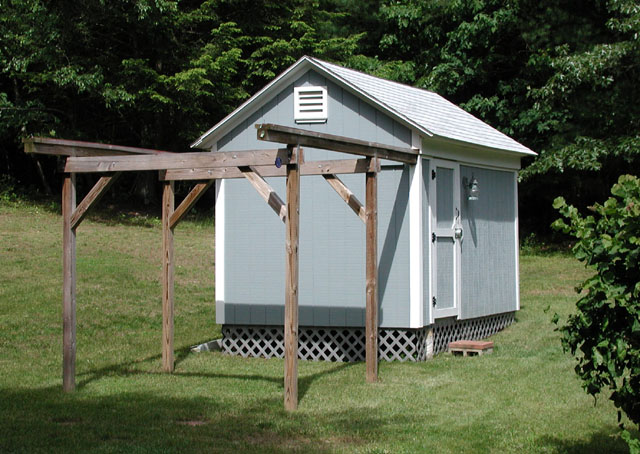
10 Sep 2006: Final coat of paint applied to the west side. The paint is a light gray. White would have been ideal (to minimize heat absorption), however white would have been a little to "bright" to go with the other buildings I have. So, I decided on a light gray as a compromise. This will keep heat absorption down and will also more closely resemble weathered wood.
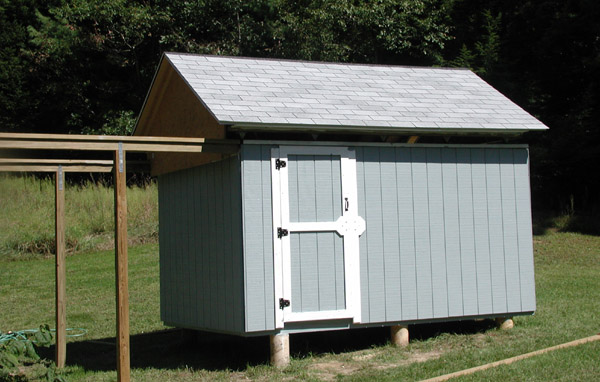
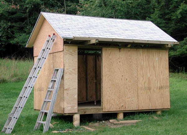
10 Sep 2006: A view with the gray paint done. Note there remains a lot of wood trim to be done yet. I wanted to get the T-111 primed and painted ASAP to prevent potential rot, mildew, etc.
10 Sep 2006: Another view of the gray paint applied.
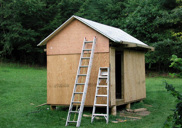
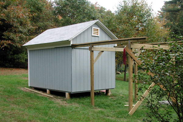
10 Sep 2006: A more distant view looking to the north.
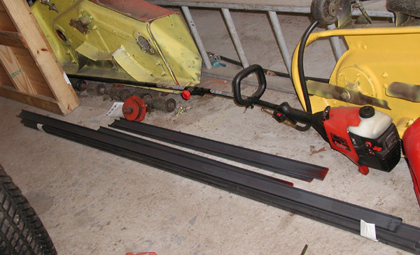
10 Sep 2006: A view of the steel "C" channel to be used for the tracks.
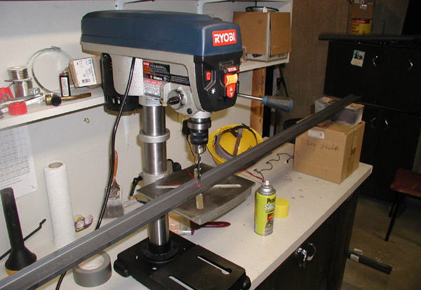
10 Sep 2006: Drilling holes in the steel channel. Screws will be used to secure the channel to the observatory frame.
10 Sep 2006: Because the roller wheels will ride in the channel, the screws must be countersunk as shown here.
10 Sep 2006: Steel track installation. I jacked the roof up slightly and slid the channels in place. This probably would have been smarter to do before the roof was completed, but this is the order I got the materials in. It worked out with minimal problems. However, if I had to do this again I'd install the steel track before the roof was built.
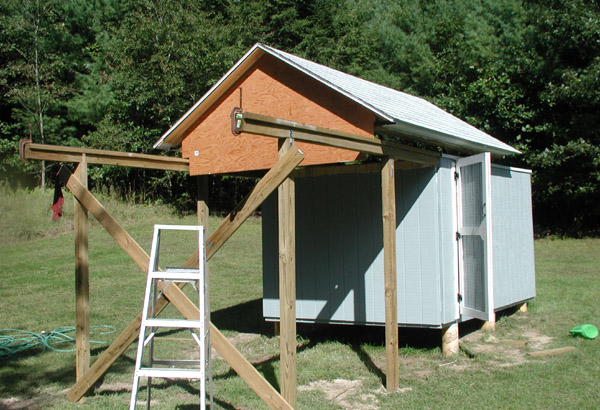
10 Sep 2006: Preparing for the very first "roll" of the roof. I added some cross members temporarily to strengthen the uprights. The roof is heavy, eventually I will add more permanent supports to the uprights, but for now I wanted to be CERTAIN of no disaster!.
10 Sep 2006: The steel track in top of the track support. I have installed "C" clamps at the end of the tracks (temporarily) to prevent the roof from rolling off the edge.
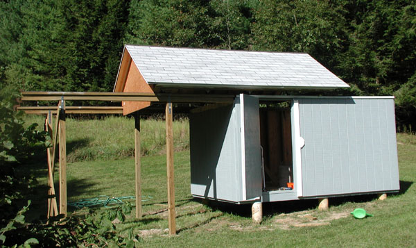
10 Sep 2006: Success! The first attempt is going smoothly. I moved the roof a few feet, then checked alignment and also made sure there was no problems with the rollers riding over the lip of the track (there were none). The roof is heavy, I can move it myself but it is close to the limits of what I can do. I will have to rig something (eventually) to assist in moving it.
10 Sep 2006: Another view of the roof moved for the first time.
10 Sep 2006: A view of the rollers on the track (on the track supports).
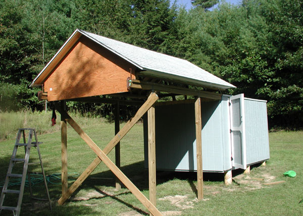
10 Sep 2006: The roof rolled almost to its farthest position.
10 Sep 2006: Another view of the roof in the open position.
10 Sep 2006: Another view of the roof in the open position.
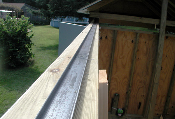
10 Sep 2006: A view of the track installed on top of the observatory walls.
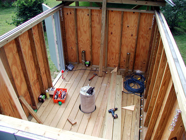
10 Sep 2006: A view of the observatory interior (with the roof open) as it stands today.
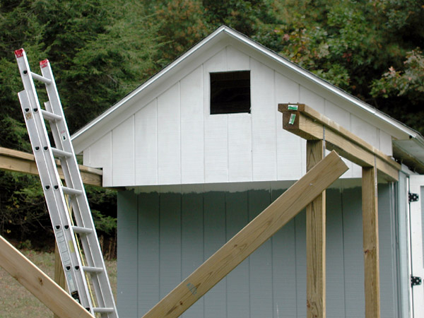
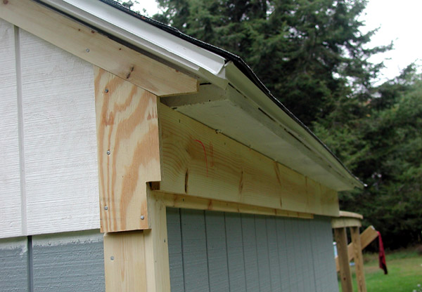
16 Sep 2006: I added the 1x8 pine boards under the eaves of the east end of the roof in preparation for the plywood end piece.
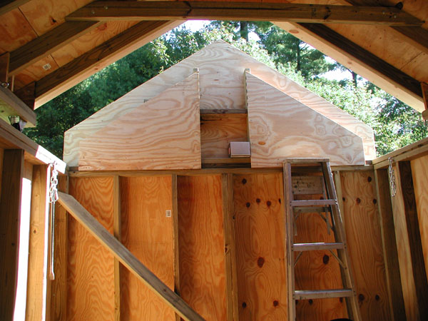
16 Sep 2006: Plywood end piece for the east end upper wall cut and installed. This part of the wall will NOT move with the observatory roof (it will stay put). This design requires fairly close tolerances and a design that will not sag over time. I am not worried about this wall obstructing my east view as I have a lot of trees in that direction (they block the view that might be had in that direction).
16 Sep 2006: Making the frame for the east end upper plywood piece. Normally one would fabricate the frame before installing the plywood onto the building, however I did it this way instead.
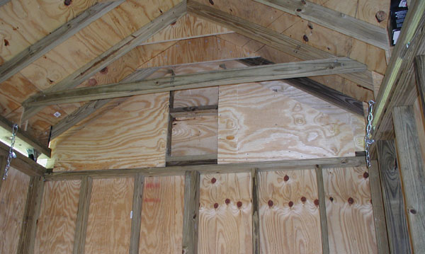
16 Sep 2006: Frame for the upper east wall installed (as seen from the inside of the observatory).
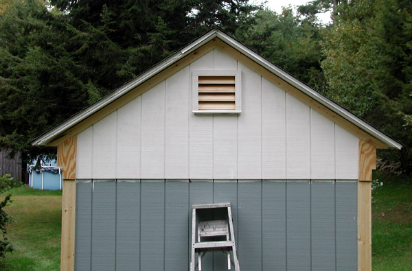
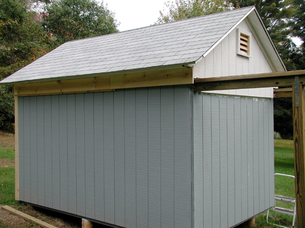
21 Sep 2006: I added the siding to the west end of the wall (upper portion). Note there is a lot of trim work yet to be done (this will hide any irregular gaps).
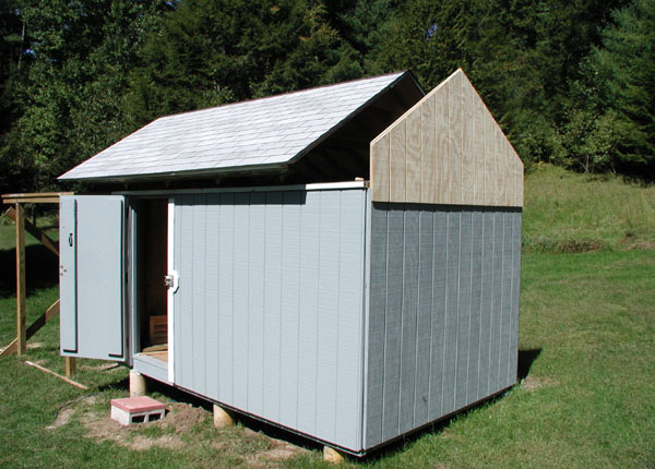
21 Sep 2006: Siding has also been added to the east wall (upper portion). The roof has been rolled slightly to reveal how this wall stays put. This design requires strong trusses (see subsequent photos) so that the roof does not sag. The clearance allowed is about 1/4 inch between the roof and the wall, I will use weather stripping to fill this gap.
21 Sep 2006: A view from inside the observatory looking at the east wall (roof slightly opened).
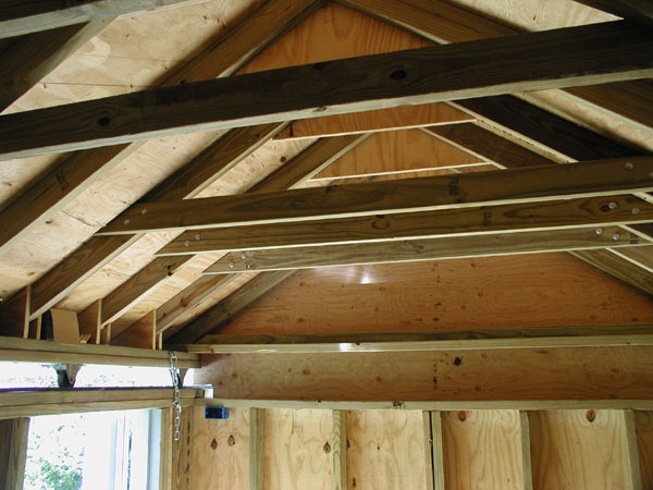
21 Sep 2006: I added a number of cross beams to the roof trusses to ensure that the roof does not sag. The cross beams are about 6 feet long, this gives me 91 inches (about 7.5 feet) of vertical working room (measured from the observatory floor to the cross beam) for the scope (over an area just under 6 feet wide). This design allows the scope to not have to be put into some weird position to allow clearance when the roof is opened or closed.
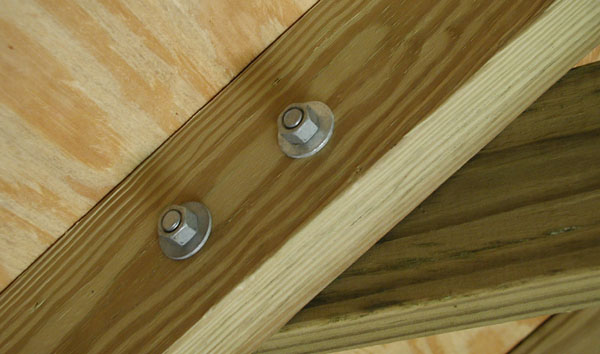
21 Sep 2006: Each cross bar is installed with four 3/8 diameter carriage bolts (galvanized).
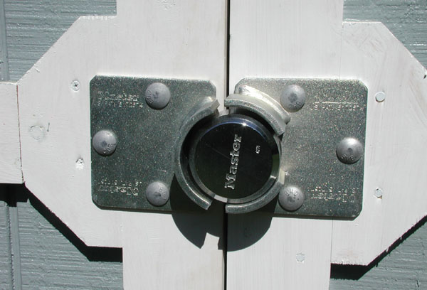
21 Sep 2006: A heavy duty locking mechanism has been added to the observatory door. Eventually I will tie this door into one of the alarm systems at the house.
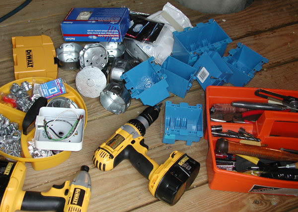
23 Sep 2006: Today is the date of Connecticut Star Party 16, however the forecast was bleak (clouds and rain for the whole weekend). Rather than sit in my van and listen to rain hit the roof, I decided to head home and do more work on the observatory. There is still a lot of detail work to be done on the exterior, but with rain that would have been a mess so I decided to work on the electrical wiring (outlets and lights). I used 12-2 UF wire for the internal wiring. Eventually I will put a sub panel in the observatory, but that will likely have to come next year (won't have time to dig the trench, install the conduits, etc. this season). For now an extension cord runs to the house to provide power. This photo shows some of the supplies and tools for today's task.
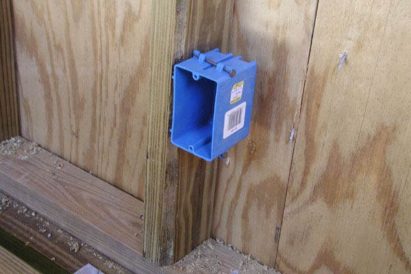
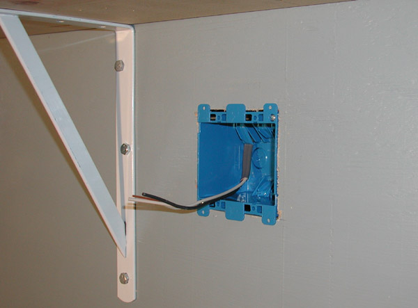
23 Sep 2006: An electrical outlet box installed.
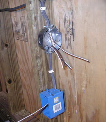
23 Sep 2006: Rough wiring in place for one of the outlet boxes.
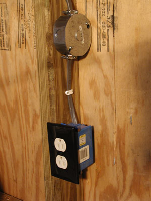
23 Sep 2006: One of several outlets all wired up. I installed a total of 6 double outlets and 2 quad outlets will be later installed as "old work" (a total of 20 places to plug things in). Sounds like a lot of outlets for an 8x12 building, but it is easy to install them during construction (and not much more money), and it seems like there's never an outlet where you want one. The quad outlets will be located near where the computer desk will be situated. I also installed 3 light circuits: one normal, one for red lights and one for the outside light. I also plan to put outlets on the pier when it is done.
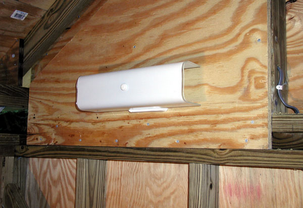
23 Sep 2006: I used an old bathroom light fixture for my "red" lights. I had a number of fixtures lying around (leftovers from other upgrade projects around the house). Rather than buying new fixtures I decided to make use of some of the ones I had (helps to clear out the basement!).
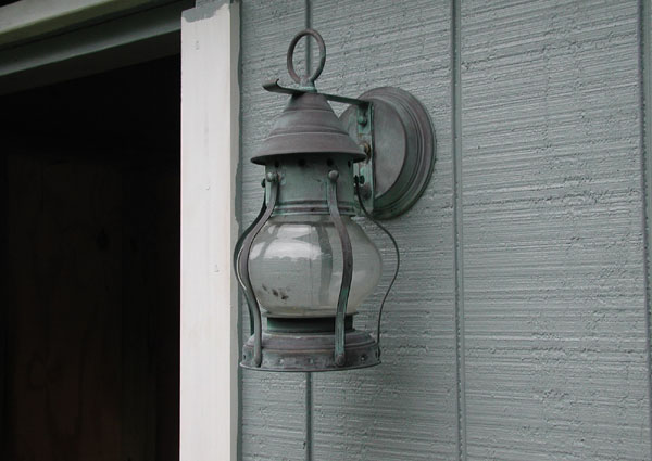
23 Sep 2006: The outdoor light fixture. I know, I know, "blasphemy" for an astronomer to install an outdoor light that is not full cutoff design. However, I like the way this light looks (it is one I took off the main house when I upgraded to full cut off fixtures). This light will have a 4 watt bulb in it, and will hardly ever be used. It is more of an "ornamental" light and in keeping with the theme of making things "look nice".
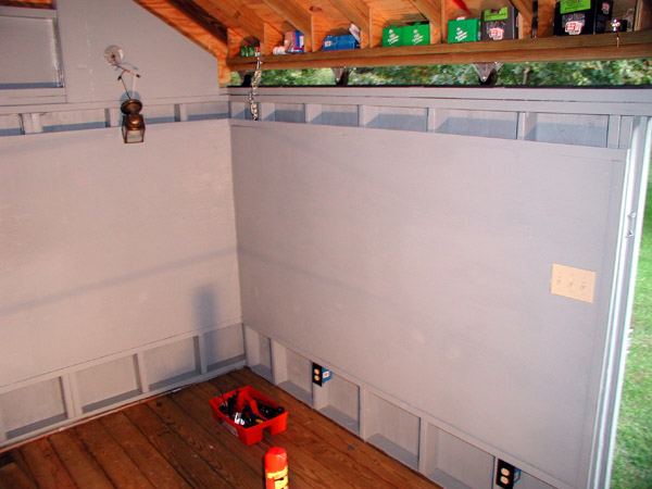
23 Sep 2006: Doing some painting in the interior of the observatory. I am only painting parts of the walls (the reason for which will become obvious in subsequent photos). A drop cloth is seen on the floor (to prevent paint from getting all over the deck boards). This wraps work for the day (about 8:15pm, totally dark outside now).
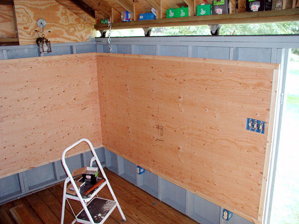
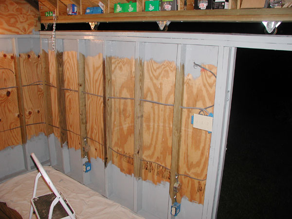
24 Sep 2006: I installed the interior walls (5/8 inch plywood and 1x2 trim). I wanted walls like this as I plan to have all sorts of charts and maps hanging in the observatory and I wanted it to look reasonably nice. The design is such that there is a 4 inch gap at the top of the wall and a 12 inch gap at the bottom. This will allow heat that may be trapped in the wall to quickly escape. This will allow the building to "cool down" to ambient more quickly than if the walls had been completely sealed (holding in warm air from the day). Note: the light fixture hanging out of the wall by its wires is my "normal" light for inside the observatory (it is another recycled fixture from other upgrades around the house). It is hanging like shown because I did not have a particular bracket for it and I did not feel like driving an hour to get one (I'll get one on my next trip out for supplies).
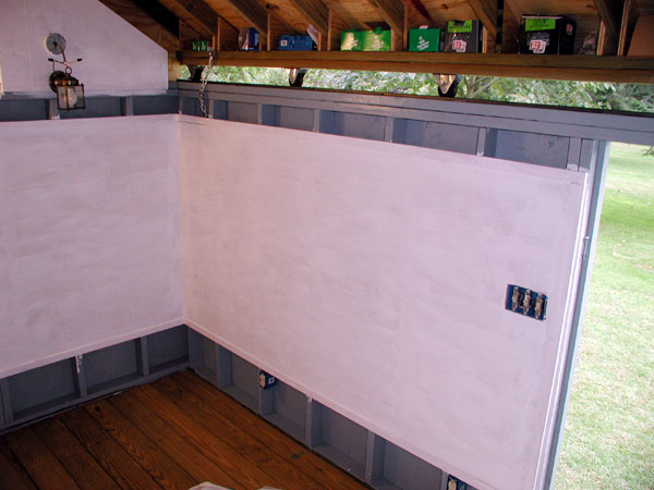
24 Sep 2006: The interior walls after a coat of primer.
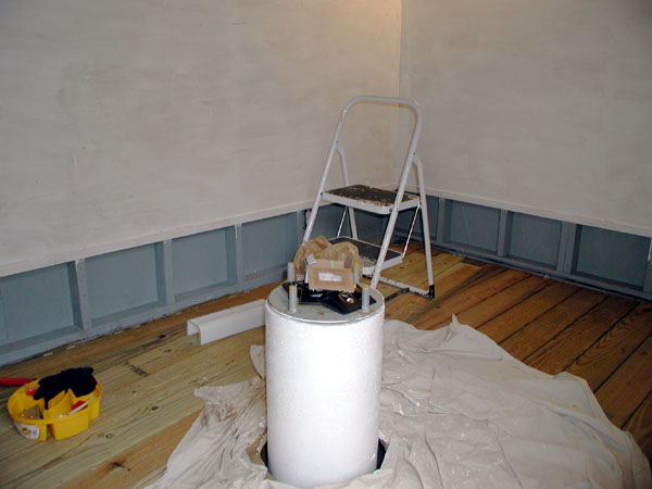
24 Sep 2006: A coat of primer has been applied to the concrete pier.
02 Oct 2006: Work resumes after a week hiatus (business trip to the west coast). The final coat of interior paint has been applied.
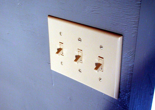
02 Oct 2006: A close up of the lighting controls. At some point in the future I may put some dimmer switches in here instead.
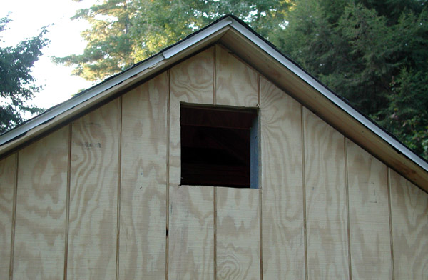
02 Oct 2006: The hole has been cut for the vent on the east end of the observatory. Used a Sawzall for this, it worked OK but I will use a sabre saw for the other end (allows a more accurate cut).
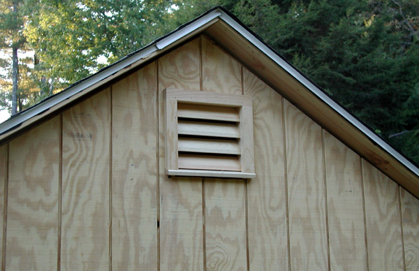
02 Oct 2006: A test fit of the vent (these were prefabricated vents I got at Home Depot, they were around $12 each).
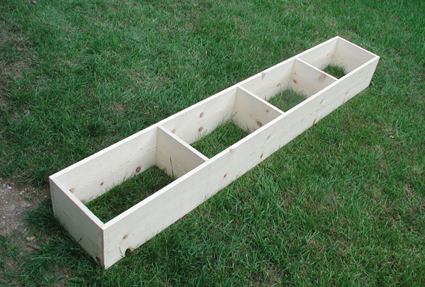
02 Oct 2006: I fabricated a shelf unit for the east end interior wall of the observatory. It is made of #2 pine boards, 1x10, it is assembled with glue and finishing nails.
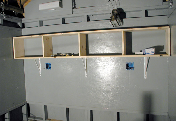
02 Oct 2006: Temporary fitting of the shelf unit (sitting on brackets that are lag bolted into the studs). I also cut the holes for the quad outlets. These are being installed as "old work" as it is easier to get the outlets exactly where you want them.
02 Oct 2006: A close up of the "rough" old work wiring.
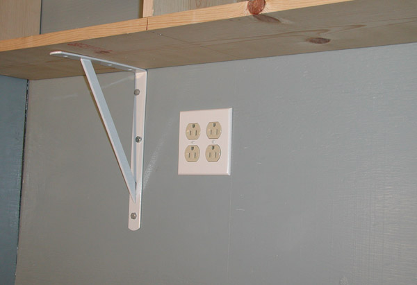
02 Oct 2006: One of two quad outlets completed.
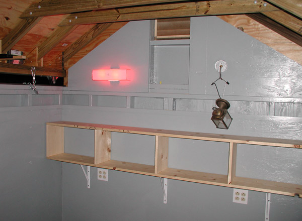
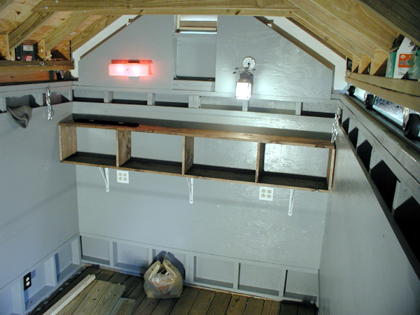
02 Oct 2006: A view of the east end of the observatory as it stands today (with normal lighting). Note the two quad outlets under the shelf. I put these up a little higher, they will be easier to get at. I plan to put a desk (or table) under the shelf area for maps, a computer, etc. The shelf unit still needs to be primed and painted.
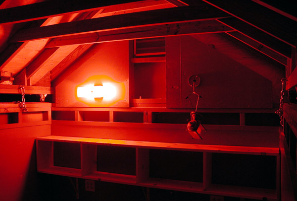
02 Oct 2006: The same basic view as above but with the red night time lighting on.
06 Oct 2006: Today will be concentrated on trim work. I cut the hole for the vent (west end) first. Then I added trim under the eaves and then rolled the roof a few feet and put primer on.
06 Oct 2006: A close up of some of the work near the eaves (more to be done here) .
06 Oct 2006: The east end with primer applied to the upper wall section.
06 Oct 2006: A view of some of the trim work for the east end. Note the gap between the trim and the roof, I allows about 3/8 inch for clearance (recall this wall stays put and the roof moves away from it, I don't want things too tight when the roof has to be closed). I will use weather stripping on the inside to seal the gap.
06 Oct 2006: The east end with the trim completed (except for primer and paint).
06 Oct 2006: The skirt boards have been added to the north side of the observatory. These roll with the roof. A little more trim work is yet to be done.
06 Oct 2006: Skirt board added to the south side of the observatory. This one I made slightly narrower than the north wall due to it otherwise being a little too close to interfering with the door. Ripping the 12 foot of board was easy with a DeWalt circular saw and rip fence.
06 Oct 2006: A view looking southeast.
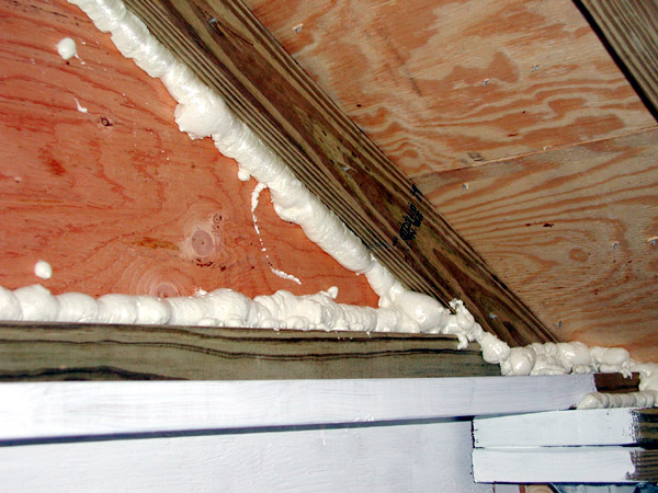
06 Oct 2006: I put expanding foam in certain spots in the interior of the roof. This is to keep bees and wasps out of places where they like to nest. Bees have been pests during construction and I want to try and discourage them from trying to make the observatory their home.
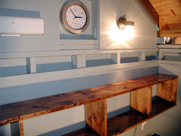
06 Oct 2006: The east wall inside the observatory. I decided to put stain on the shelf unit instead of paint (I had a can with just enough left to do the job). I'll give it a few coats of polyurethane when I a chance.
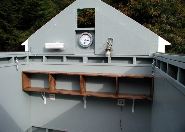
10 Oct 2006: The shelf unit has a coat of polyurethane. Also, a clock has been added and more painting has been done.
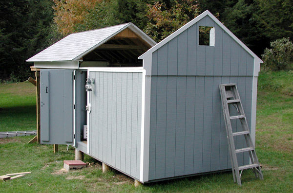
10 Oct 2006: Several hours were spent painting woodwork (a lot of detail work, kind of a pain but it has to be done). This view shows the south and east sides of the observatory with woodwork painting pretty much done.
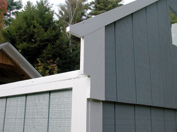
10 Oct 2006: Detail of the woodwork at the southwest end of the observatory.
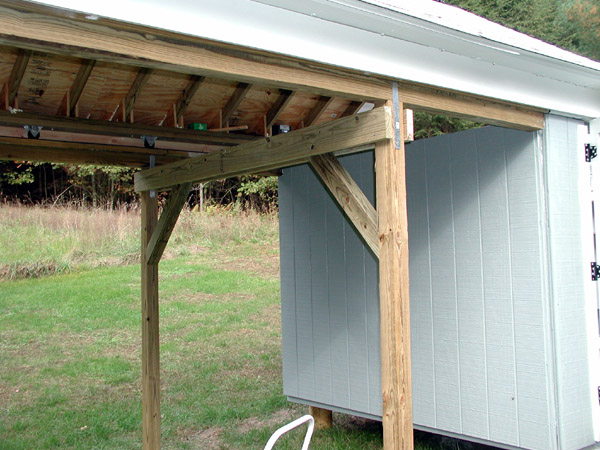
10 Oct 2006: Today I also cut and temporarily installed 2x6 beams and angle sections of 4x4 beams to the track uprights. These will greatly strengthen the structure. I do not need to put any in the east west direction as this axis is held firm by the steel track on top of the beams. These 4x4 angle pieces will be secured with 1/2 inch diameter 8 inch long carriage bolts (have to get them on a supply trip tomorrow).
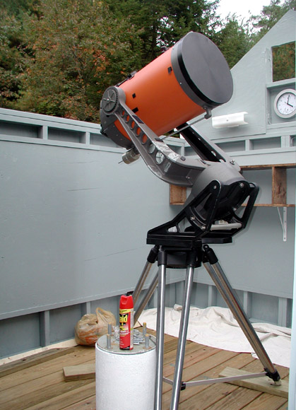
10 Oct 2006: A major step forward! The telescope has been moved to its new home! However, for now it is on its tripod; I placed the scope near the concrete pier to measure how long of a piece of steel I need to order from the steel supply shop. I will use 8 inch diameter steel tubing (1/4 inch thick) to extend the pier to the proper height. The top and bottom plate of the steel pier will be 1/2 inch thick steel plate. I determined that the length of steel needed to allow the scope to reach -35 degrees declination is at least 17 inches. I may make it a bit longer to get to maybe -38 degrees south. Not that the view will be too good at that angle, but at least I'll have access to it if needed.
10 Oct 2006: A view from the stepladder.
10 Oct 2006: A view looking northwest with most of the woodwork done and painted. A few pieces of trim are left to be done and some more work on the track support uprights awaits. The boards like an "X" on the track support posts are temporary and will soon be removed.
10 Oct 2006: A view looking southeast.
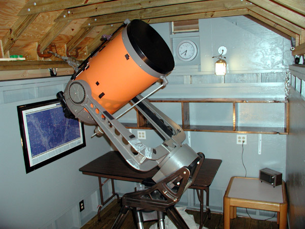
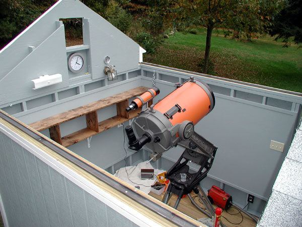
10 Oct 2006: A view inside the observatory (as of today) with the roof closed. The shelf now has 2 coats of polyurethane. I also installed an Orion DeepMap 600 on the north wall near the scope. I put it in a poster frame to protect it (plus it looks better). I do have much more detailed star charts, but this is a great map to have for quick reference and casual observing. I have a second DeepMap 600 that I will also install (with the opposite side visible). I also added a banquet table and an office table. Until I get the winch to move the roof I am using a come-along to open and close the roof. Anticipation for a grand opening is increasing!
11 Oct 2006: I added all the hardware (8" long 1/2" carriage bolts) to the track support uprights and beams. This section is just about now completed. The track support uprights were made to slope very slightly to the west so that rain will run out of the tracks (and not into the observatory).
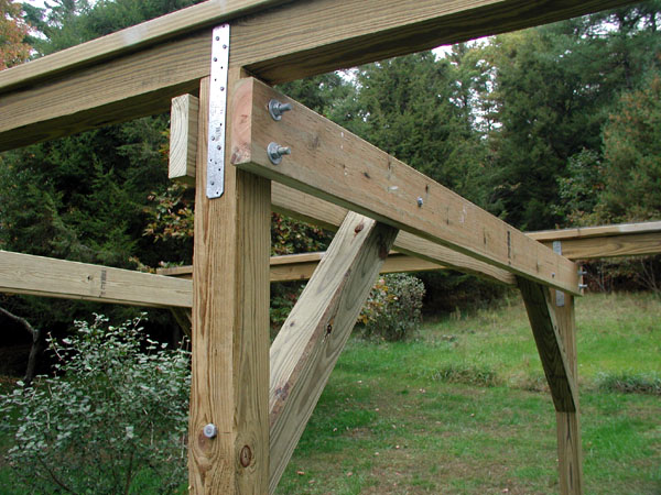
11 Oct 2006: A close up of the track supports. Hardware consists of 8 inch 1/2 inch diameter carriage bolts, 8 inch long x 1/2 inch lag bolts, and 5/16 inch diameter 4 inch long lag bolts (all galvanized). One thing I've learned from this project: all the hardware adds up! I bet I spent several hundred dollars on bolts, nails, screws, etc.
11 Oct 2006: A new light. I was going to get a bracket for the old light I had, as it turns out it is actually less costly to buy a whole new light! The bracket was $4.99 and the new light was $3.97. I was in Home Depot and overheard a worker training some new employees... I heard him say "Always try to sell accessories, that's where we make all our money". In this case, the bracket (which probably costs 25 cents to make) ended up with an end cost of more than the entire new fixture. Also the shelf unit has 3 coats of polyurethane now. Once it is dry things can be loaded onto them.
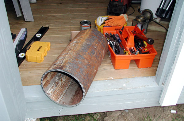
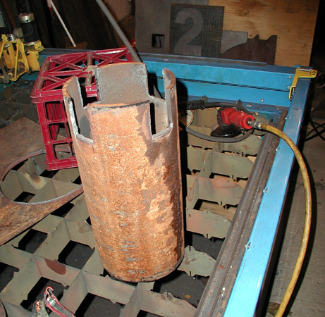
11 Oct 2006: The steel pipe section to be used for the telescope pier. I was able to get surplus steel (that's why it is rusty), this saved some cost. It is 8 inch inside diameter and about 3/8 inch thick. The cost was around $55, this included two clean cuts at the steel supply place.
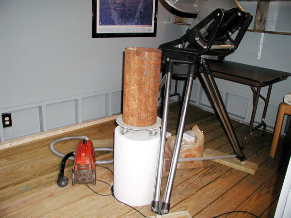
11 Oct 2006: The steel pipe section set up on the concrete pier just to get an idea of how things will look. The pipe section has to have steel plates added to both ends. Fabrication and assembly of the steel pier will be the next major task.
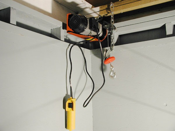
28 Oct 2006: Another multi-week hiatus on progress (due to business trips). I ordered an electric hoist from Northern Industrial to assist in moving the roof. The unit is capable of 220 pounds single line and 440 pounds double line. I found that the single line mode worked fine (but a little fast). There are pulleys that allow me to open and close the roof without the need for a hoist on each end of the observatory (basically I reverse the direction of pull when needed by running the hoist line over a pulley at the far end of the observatory. When I opened the roof (and closed it) I found it made a horrendous loud squealing sound! The nearest neighbor is about 350 feet away, however in the summer (with windows open) I had a bad feeling that this noise (it's fairly quiet out here) would cause disturbances in the middle of the night. From a distance it would sound like a massive attack on some kind of wild animal! To try and quiet things down I squirted WD-40 into the wheels that allow the roof to roll. After a few "back and forth" motions to open the roof it quieted down and there was no more squealing. I then found out that not only did it quiet things down, it made the roof easy enough to roll by hand WITHOUT the hoist! So, all it really needed was a $3 can of WD-40, but I spent $120 on the hoist! Not a big deal however. If there is a heavy load of snow on the roof hand rolling of the roof may still be too difficult, so the hoist is available for such times. If I find I never use it I can always move it to the garage for work on power equipment.
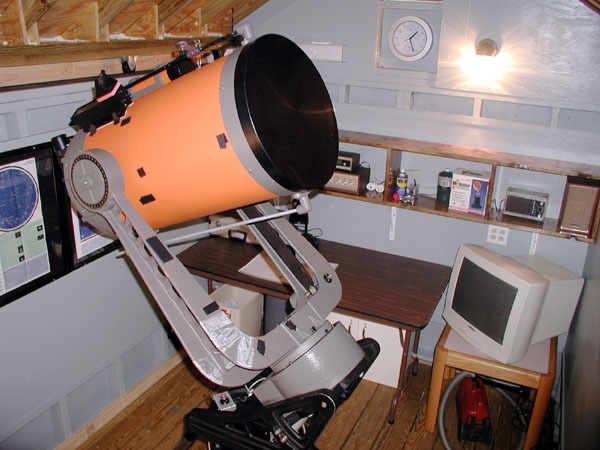
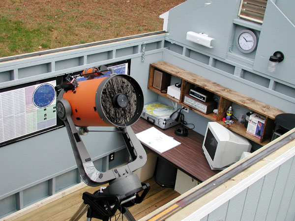
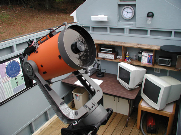
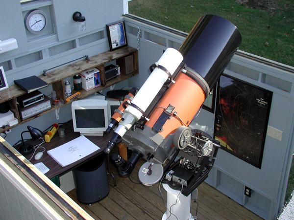
28 Oct 2006: A view of the observatory with a few more additions. I moved the scope so it is right over the pier (the steel pier still needs to be fabricated). I also added another star map, a cabinet (under the table), a sound system, a gooseneck lamp with red bulb (on the table), and a 20" monitor (a spare one that was hanging around the house, eventually when I get a computer in the observatory it can be used). A trash bucket has also been added along with a few of the scope's accessories.
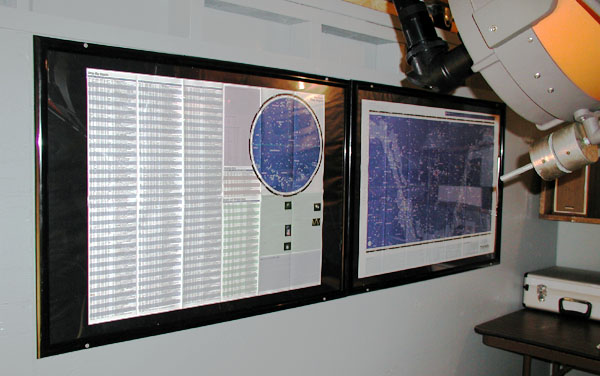
28 Oct 2006: A view of the Orion DeepMap 600 star charts (both in poster frames) mounted on the north side of the observatory wall. I bought 2 maps so that both sides of the map could be displayed at the same time.
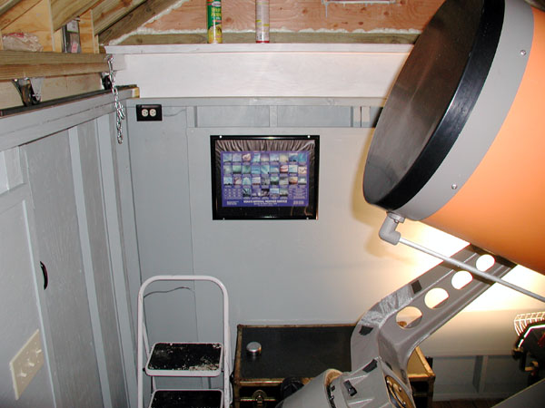
28 Oct 2006: A view of the east end of the observatory. A framed poster of various cloud types has been added. Also the trunk that holds the C14 optical tube is present (finally can get it out of the garage).
05 Nov 2006: A view of the inside of the observatory from the high stepladder.
05 Nov 2006: A view of the inside of the observatory.
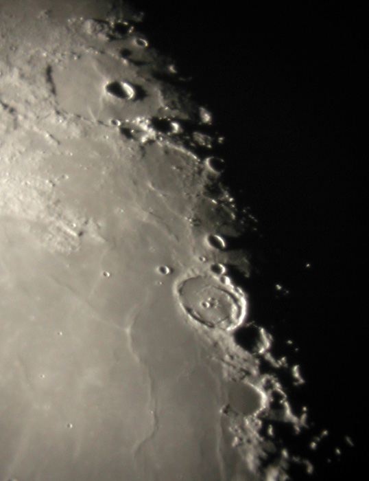
10 Nov 2006: My first "finished" photo taken from the observatory. This close up of the Moon was taken around 4:20am on 10 November 2006 using an Olympus C3030Z digital camera (old by today's standards) using afocal method with a Televue Plossl 32mm eyepiece. I actually took around 100 photos this morning, but only the good ones are saved off. When I say "finished" photo basically it means this is one of the good ones. The large crater to the lower right of center is Posidonius, it is about 60 miles wide. The smallest crates visible in this image are about 2 miles across. In theory, the C-14 can resolve objects on the Moon that are around 1/3 mile across, however atmospheric conditions on Earth never allow resolution to that level of detail.
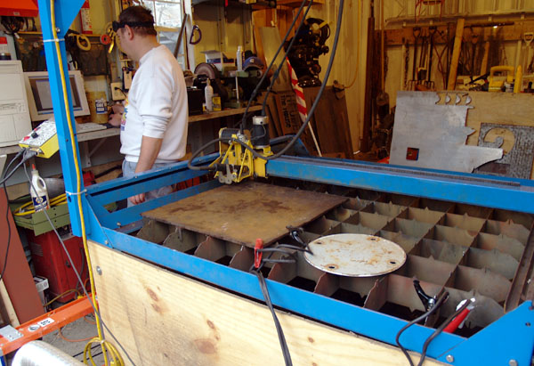
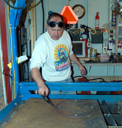
12 Nov 2006: Setting up the Plasma Cutter to make parts for the steel pier. The plasma cam machine is computer controlled. Basically the part to be cut out is drawn on the computer and then the computer drives the machine's cutting head. This is 1/2 inch thick steel plate that is to be cut. The stud alignment plate (cut last fall) is shown sitting on the machine. One part to be cut is a duplicate of this (albeit in 1/2 inch thick plate vice 3/16 inch plate).
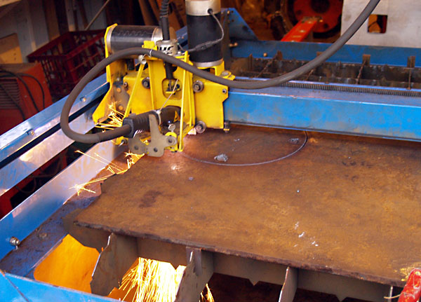
12 Nov 2006: The Plasma Cam machine in action, cutting out one of the pier base parts.
12 Nov 2006: One of two parts to be cut after cutting (and before removal from the machine).
12 Nov 2006: The final part. This will be the base plate of the pier, this will bolt onto the concrete pier that was poured earlier in the year. The holes are 7/8 inch diameter. The holes were cleaned up on a milling machine. A second similar part was cut, this one did not have holes in it (the second part is the top of the pier to which the telescope will bolt to).
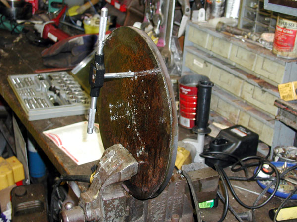
19 Nov 2006: Tapping (threading) the holes on the pier top plate. 9 holes were drilled (holes were drilled at 5/16 inch diameter). The C14 wedge has 3 elongated holes (to facilitate polar alignment). Because I cannot be 100% sure I can line up the pier exactly to the pole I drilled 9 holes (vice 3) in the pier top to allow a greater range of adjustment. The final tapped holes will take 3/8" coarse thread bolts. The tapping of these 9 holes went fairly smooth despite the thick steel (a decent amount of cutting oil helped things go smooth).
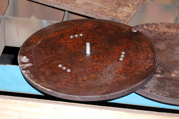
19 Nov 2006: The completed top plate of the pier. There is a 3/8 inch threaded stud (actually a bolt welded into place) to allow centering of the C14 wedge. The bottom plate is below the top plate.
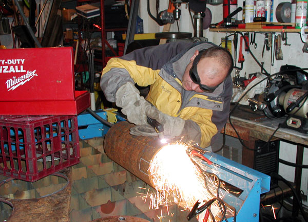
19 Nov 2006: Using a plasma cutter to carve out portions of the steel pier section. The pier section is 8 inch diameter (inside diameter). When I did the "dry fit" of everything I noticed that the thickness of the pier wall (about 3/8 inch) would interfere with nuts and washers used to bolt the steel pier up to the concrete pier. Thus, rectangular sections (about 2 x 3 inches) of steel needed to be cut away to allow easy installation of pier mounting hardware.
19 Nov 2006: The steel pier section after cutting away sections to allow nut and washer installation. Hand guiding the plasma cutter does not make for precision cuts. However, I am not looking for glamour here... functionality is the primary goal.
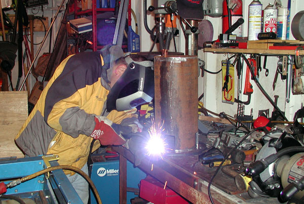
19 Nov 2006: Welding the bottom pier plate to the steel pier section.
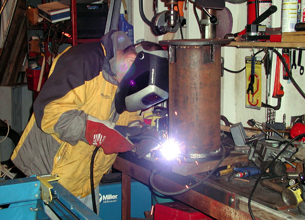
19 Nov 2006: Welding the pier top plate onto the pier assembly.
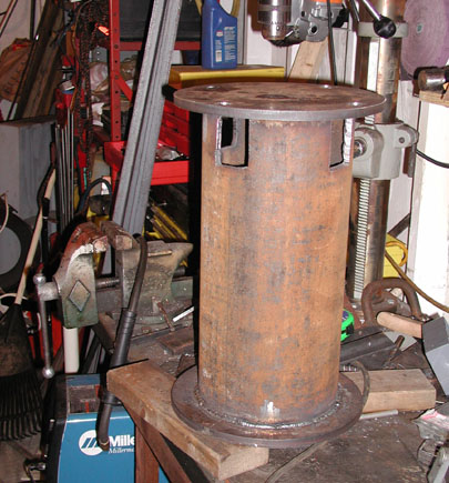
19 Nov 2006: The pier assembly after welding (things are pretty warm after welding, have to let it cool before handling!).
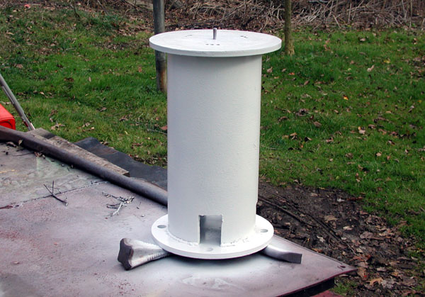
20 Nov 2006: The pier assembly after receiving a coat of primer and paint. The pier was first degreased (lots of cutting oil was on it), dried and then wire brushed to remove rust (recall that the pier pipe was surplus steel). Today was a bit cool (40 deg) for painting, to assist paint setting I placed the pier assembly on a wood stove for an hour or so. The pier section weighs about 90 pounds and can hold a lot of heat!. I painted the pier white so that heat absorption would be minimized (important for better seeing conditions).
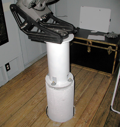
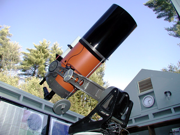
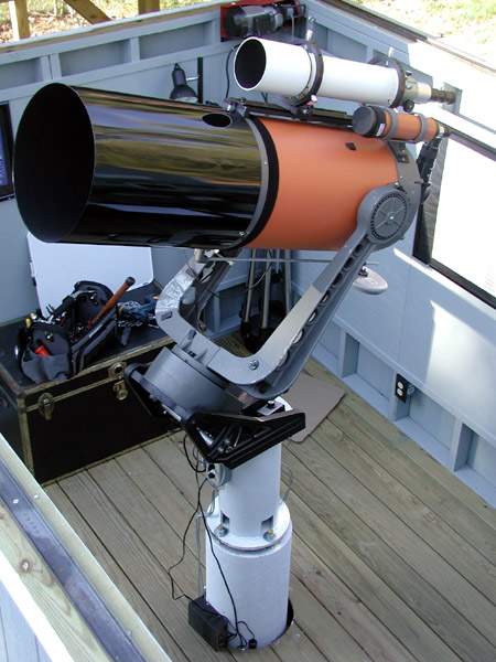
21 Nov 2006: Initial installation of the C14 on the steel pier. The pier is secured to the concrete pier with 4 washers and four 3/4 inch nuts.
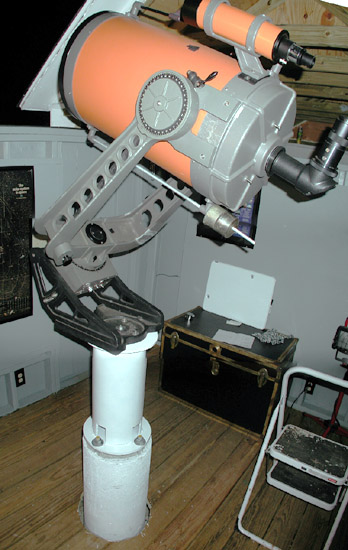
21 Nov 2006: A panoramic view of the C14 on its permanent pier. This close quarters panoramic shot is distorted and exaggerates the size of the optical tube! I did some initial steps to final polar alignment (using the declination drift method). The pier is VERY solid. I was using 782x magnification to do the declination drift adjustment. I gave the concrete section of the pier a good kick and the image jumped not very much and then calmed down very quickly. I was able to detect no image disturbance whatsoever (at 782x !) when jumping around on the observatory floor. I ran out of time (and now it is supposed to be cloudy for a while) so I will need to do more fine tuning on the polar alignment. Things are nearly functional now!
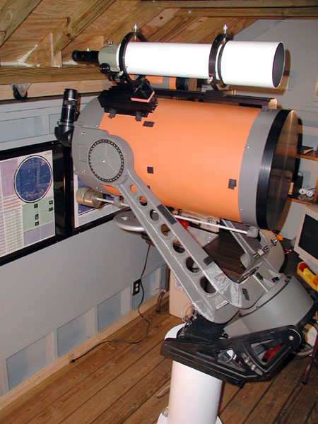
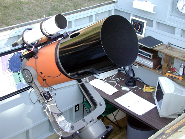
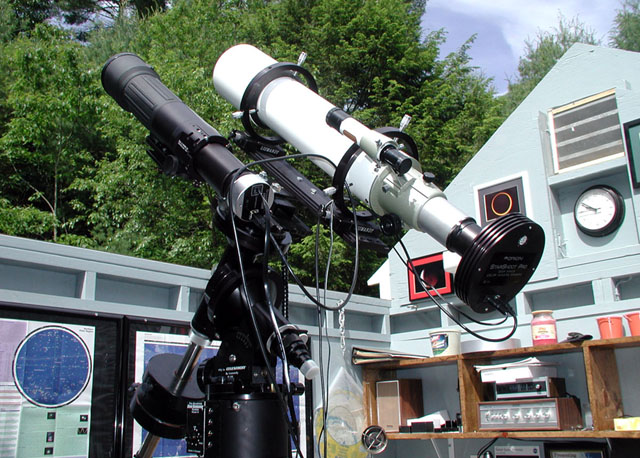
07 Dec 2006: Addition of a Vixen 102 ED refractor (mounted piggyback on Losmandy hardware). The Losmandy hardware wasn't cheap (around $325 for the dovetail plate and two scope mounting rings) but it is very well made and very nicely finished. There is also a Telrad near the observing end of the Vixen scope. The C14 is a great scope, but it does have a narrow field (about 1/2 degree at best). The Vixen will complement that, allowing excellent views of wide field objects. It will also serve as an excellent scope for photo work, or if needed, an incredibly powerful finderscope.
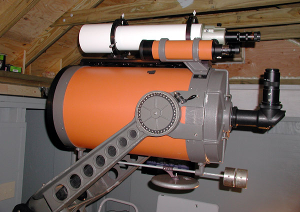
07 Dec 2006: Another view of the Vixen 102 ED refractor addition. This view also shows some of the balancing items I had to add (to accommodate the Vixen). I used a 10 pound barbell weight (from Wal Mart) mounted to a photo adapter using a 1/4-20 bolt. This scheme worked out pretty well, although I may beef it up at some point. I just need to add a little more balancing weight on the opposite side of the tube (to counteract the 10x70 finderscope) and then things will be pretty well balanced!
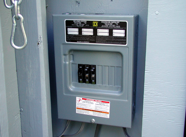
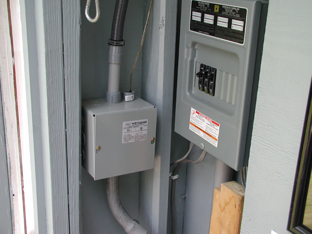
29 Dec 2006: Addition of the circuit breaker panel for the observatory. The wiring back to the main house is just a 12-2 extension cord for now (I'll do conduits and 8-3 UF cable in the spring for the final power hookup). There are 3 circuits wired at this time.
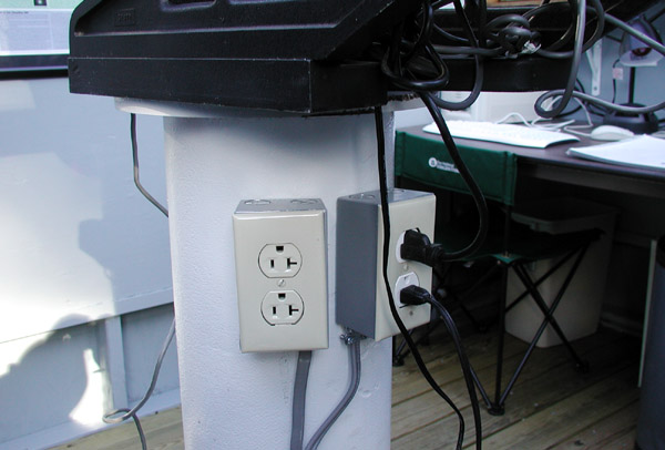
29 Dec 2006: Two outlet boxes added to the observatory pier. One is 20A the other is 15A. These will eliminate the need to have power cords plugged into wall outlets (trip hazard). The 20A outlet is for a hair dryer, since I have no more hair my 1977 vintage hair dryer is now relegated to dew removal and warming up boots in the winter!
29 Dec 2006: Addition of a new aluminum Astrozap Dew Cap. The old Tuthill dew cap I was using was kind of a pain to put on and take off, this new dew cap is permanent. It was not cheap ($245) and it seems a little flimsy for what I was expecting for that cost, but it appears to be the best available on the market. The cost is likely high because not too many of these are made (hard to recoup tooling costs on such a low production item). I also installed several Kendrick dew heaters and a control for them. I also added a 2 pound barbell weight to counteract the weight of the 10x70 finderscope on the other side of the optical tube. It is held on with tie-wraps... not glamorous, but the intent is met.
29 Dec 2006: A view looking to the northeast.
29 Dec 2006: A view looking to the northwest.
29 Dec 2006: A view looking to the southwest.
29 Dec 2006: A view looking to the southeast.
For the time being I will use this Celestron fork mount. It is older (by today's standards) and probably has a fair amount of periodic tracking error. I plan to upgrade the mount at some point. I considered the Software Bisque Paramount ME, however at around $13,000 it is for practical purposes not affordable to me and I can't really justify that kind of expense anyway (it alone would cost more than the observatory and the scope combined). The Losmandy G-11 mount is not really large enough (in my opinion) although Celestron does put the newer C14 scopes on a very similar mount (it is OK for visual but probably not good enough for photography work). The Losmandy HGM Titan is one mount I am looking at that would serve the purpose, but at $6500 it too is quite costly. I'll have to think about it more over the winter! In the meantime, I basically now have a telescope of considerable capability that is ready to use with only a few minutes notice. A nice feeling!
The major task remaining to be done will be the installation of permanent underground power and conduits for cables. This will allow me to run coax cables, phone lines, etc to the observatory. I will then potentially be able to remotely control the scope from the warmth of the house and it will also allow me to do live uploads (for public viewing) of brighter targets such as the Moon, planets, the Sun, etc.
The observatory is basically ready for use. I have used it a number of times already, and I cannot state how convenient it is to not have a major setup and takedown for an observing session. I was out on 27 December looking at the Moon. Within 5 minutes it clouded over... in the old days I'd have had a fit (all that work to set up and then it clouds over)! Now when it clouds up I simply pull the roof closed and go back in the house.
Due to being excessively busy I did not get the underground wiring in, however the extension cord (for power) it serving just fine. I finished up all the trim work and did some more fine tuning inside the observatory. I did learn that using CRT computer monitors outside in a non climate controlled environment does not work. I turned on a monitor when it was damp and it sounded like a pack of firecrackers going off inside the case! It no longer works. I tried an LCD monitor and it seems to work just fine outside, even in 20 degree temps!
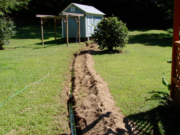
I finally had a chance to dig the trench for the underground wiring to the observatory. Permanent electricity is now out in the observatory along with a number of other cables (power cable was put into one conduit, signal cables were put into another). I ran the following cables to the observatory: two RG-6 coax cables, one Cat 5 Ethernet cable, two Cat 3 voice grade lines, and 4 twisted pair general purpose signal lines. This amount of data cables should hopefully provide for any future growth that may be needed. The photos below show these most recent activities...
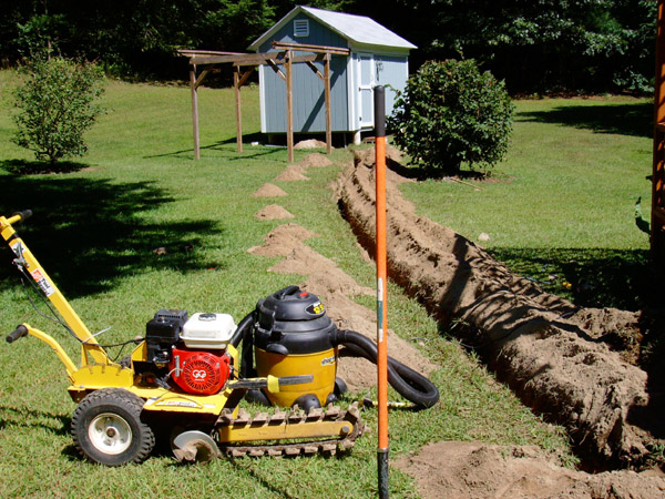
31 August 2008: Trench digging day. As expected, the rocky soil proved to be a major challenge for the trench digger. This shot shows the finished trench and the machinery used to do the job. The shop vac was used to suck dirt out of the trench. Trenchers tend to throw about 1/4 of the soil they dig back into the trench, and I wanted as much depth as I could get. So, I used the shop vac to suck all the excess dirt from the dug trench. This method worked pretty well, FAR easier than reaching down by hand to pull all the dirt out. The piles of dirt along the length of the trench are all dirt piles dumped from the shop vac.
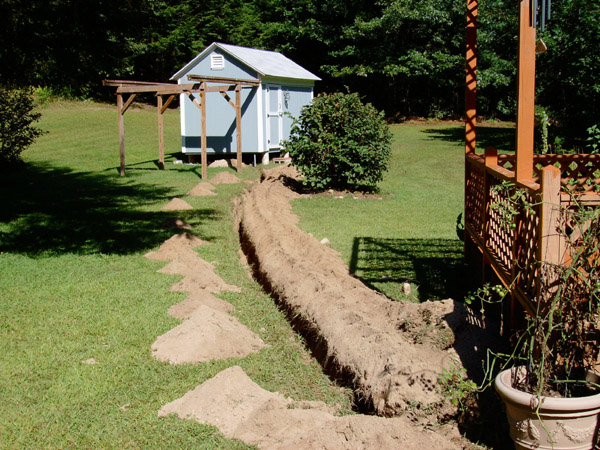
31 August 2008: Another view of the trench. Due to the layout of my deck I had to run the conduit under the deck and then through the foundation. I do not have any photos of the foundation drilling work. For this (significant) job I used a Hilte to drill a number of holes, then I used an air powered hammer to blast out the rest of the excess concrete.
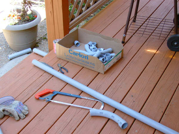
01 Sep 2008: Conduit installation day. Here are a few of the tools and materials used. I ran 2 conduits, a 1.25" for the 8-3 cable and a 1" for the signal cables. Both were buried in the same trench.
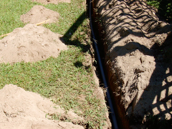
01 Sep 2008: This shot shows one of the conduits installed in the trench. Due to the number of turns I had to negotiate, I could not pull the cable through the conduit. Instead I laid the cable out and installed the conduit over the cable. Normally UF cable can be directly buried in the ground, however I prefer the extra durability a conduit provides.
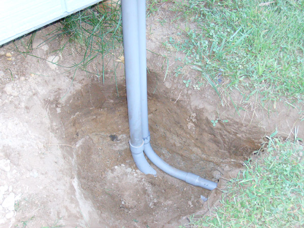
01 Sep 2008: A shot of the conduits coming up into the observatory. Note that freeze expanders have NOT yet been installed (these prevent the conduit from binding and jamming when the ground freezes).
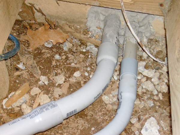
01 Sep 2008: This shows the conduits where they enter the foundation of the house (this was a pain to work on as the only entrance point was directly under my back deck). The hole in the foundation was patched with hydraulic cement.
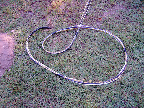
01 Sep 2008: Here's a shot of one end of the umbilical cord of signal cables. To make this up I ran each cable out to its full length (about 130 feet) and then taped the bundle together. This final assembly was installed in the conduit. Inside the observatory it terminates at a metal 6x6 junction box (and also inside the basement there is another junction box).
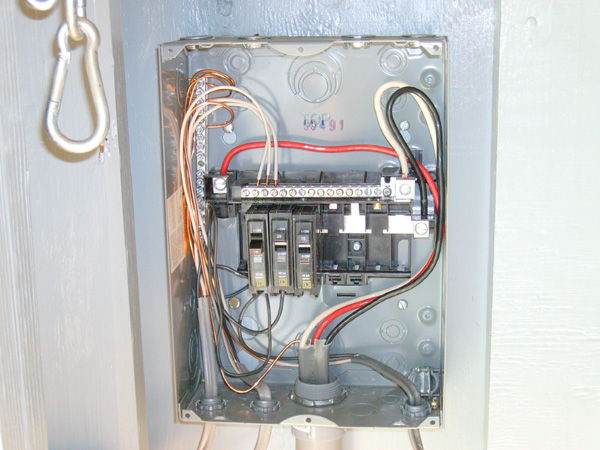
01 Sep 2008: Here's a shot of the final connection of the 8-3 cable to the sub panel in the observatory. This provides 40A 120/240 VAC service (more than I am ever likely to need in the observatory but I like to have room to grow if required). NOTE: DO NOT use this photo as a wiring guide if you are wondering how to wire a sub panel. If you are doing your own electrical work, make certain you are qualified to do the work. If not, hire a licensed electrician so that you avoid killing someone or burning down your house.
02 Sep 2008: Here's a view of the partially buried trench. A length of safety tape runs the length of the trench about 6" down from the surface. This will provide some warning should someone start digging here in the future.
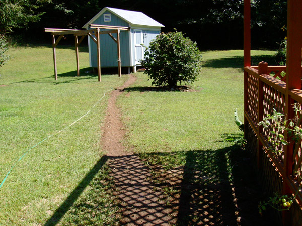
02 Sep 2008: The fully buried trench. Although it would seem like an easy job, burying a trench back up is a big job. To make it settle properly, I put about 4" of dirt back in, sprayed it with water, and then walked on it several times. This process was repeated a number of times until the trench was completely buried. Doing it this way takes longer but it prevents sinkholes from appearing later on.
I added some decorative lattice to the base of the observatory. Also the Ethernet and other cables are wired up. I swapped out the C14 (temporarily) to do some astrophotography using smaller scopes. The photos below show these most recent activities...
June 2009: Decorative lattice has been added around the base of the observatory.
June 2009: Various electronic services are now wired up, including telephone, Ethernet, video (RF or baseband) and a standard audio line. The Ethernet allows me to start imaging (using the computer in the observatory) and then I can go in the house and move files to the house computer for processing and saving. A nice feature that will be very handy once the really cold weather arrives!
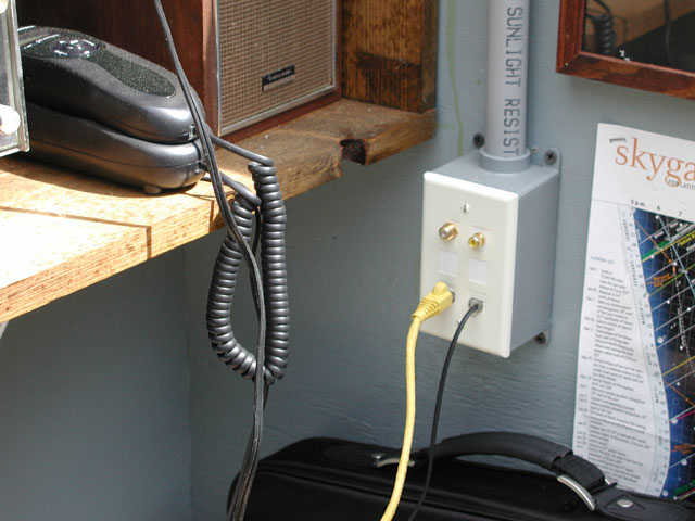
June 2009: A utility junction box where all the services (other than electricity) come in.
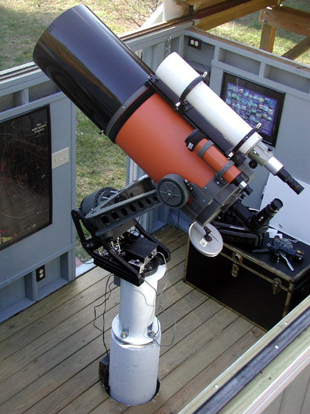
June 2009: The C14 has been swapped out of the observatory temporarily. The older C14 fork mount is not autoguider compatible... I am currently using a Losmandy G-11 which is autoguider compatible (necessary for good astrophoto work). Here a Vixen 102 ED (4") refractor is the main imaging scope and a Vernonscope 80mm scope is used for the Orion Autoguider. Both of these scopes are mounted side by side on a custom adapter plate that I made.
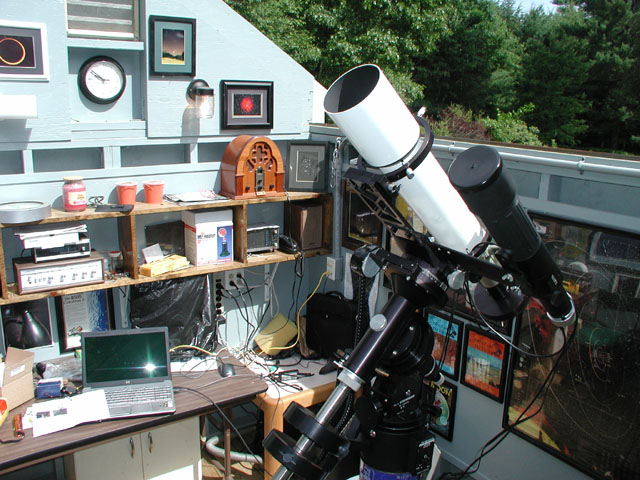
June 2009: Another view of the Vixen astrophography setup.
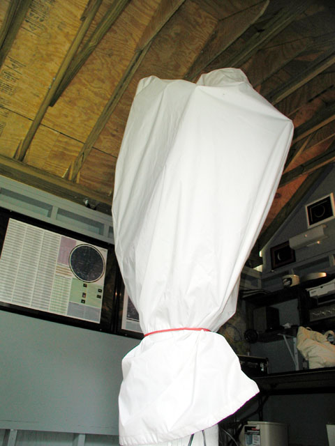
June 2009: A view of the scope with the dust cover over it.
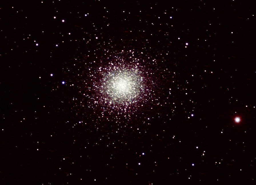
June 2009: My first decent shot of M13. This is a one hour (12x300 second) exposure of M13 through the Vixen 102 ED scope using the
Orion StarShoot Pro Deep Space CCD Color Imaging Camera.
Guiding was handled by the
Orion StarShoot AutoGuider
(it works great). I am now at a point where I should be able to do routinely decent imaging. The next major step will be to upgrade to a higher capacity mount so that the C14 can be used for imaging!
Use your browser's "back" button, or use links below if you arrived here via some other path:
This page is part of the site Amateur Astronomer's Notebook.
E-mail to Joe
Roberts
Images and HTML text © Copyright 2005-2009 by Joe Roberts. Please request
permission to use photos for purposes other than "personal use".