
Rev (-) 26 May 2001
© 2001 By Joe Roberts
Introduction: This article will illustrate the characteristics of AC Voltage waveforms generated by a Radio Shack (Cat No. 22-138) AC Power Inverter. Such devices are used to convert 12 VDC to 115 VAC. For comparison, the AC waveform from a standard household outlet will also be characterized. Both time and frequency domain analysis was performed on the waveforms.
Method: The AC Inverter was connected to a 12 VDC Deep Cycle battery and a 100 W incandescent bulb was plugged in and turned on to give the inverter a load. The AC voltage waveform was applied to a voltage divider circuit, and the output of that circuit was connected to the line in jacks of the sound card in the PC. Using Magix Music Studio software, the "music" was recorded for a period of about 5 seconds. Using the editing capabilities of Magix Music Studio, a portion of the data was saved as a .WAV file. The .WAV file was then imported into MATLAB where time and frequency domain analysis was performed. The method for acquiring the signal from the standard AC wall outlet was similar, except that an isolation transformer was used (this was done to remove any possibility of damaging the PC).
WARNING: If you want to try and duplicate the method described here, be certain that you are 100% confident in your ability to properly and safely make the necessary connections. Failure to do so can result in a blown computer, a severe shock, or in extreme cases, death!
Results: For comparison purposes, we first present the results of the analysis on the standard household AC waveform. The voltage at my house tends to run on the low side, however for this article we are mainly interested in the harmonic content of the waveform, not the absolute voltage level. Figure 1 below shows a few cycles of the AC waveform:
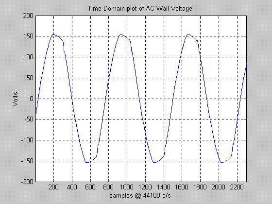
As can be seen in Figure 1, the waveform is not a perfect sine wave (AC power in general never is). Overall the waveform is not all that bad however. In Figure 2 below we show a frequency domain plot of the waveform of Figure 1. Basically, this is a plot that shows the relative magnitude of the harmonic (and other) components that make up the AC voltage waveforms:
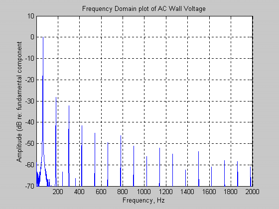
The horizontal scale of this plot only goes to 2000 Hz because there was very little energy above this point. The large line at 0 dB level is the 60 Hz component of the voltage signal. The next significant line as the 3rd harmonic at 180 Hz. As is typical for distorted sinusoidal signals, the odd harmonics are predominant (even harmonics are very small). From the plot we see that the 3rd harmonic (180 Hz) is about 27 dB below the fundamental (this equates to a level of about 4.4% that of the fundamental, or in terms of power, about 0.2% of that delivered by the fundamental. Although I did not explicitly calculate the total power of the harmonics, it is in the vicinity of a few percent. Overall, this is pretty decent quality power in terms of waveform quality. I measured the frequency to be right on the money, 60 Hz.
Now we turn our attention to the voltage waveform of the AC Inverter. Figure 3 below shows a few cycles of the voltage waveform at the output of the inverter when loaded to about 50% capacity:
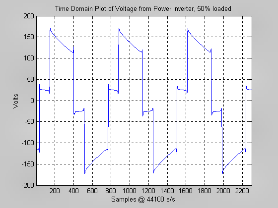
One look at this plot shows that the waveform is very different from that seen in Figure 1. This waveform contains many sharp edges which translates to a lot of high frequency energy being present in the waveform. From this, we can almost certainly conclude that the circuitry used in this particular AC Inverter is not one of the so called "sine wave" inverters. The waveform shown in Figure 3 is basically a "modified square wave" type signal. Next we show a frequency domain plot for this signal, see Figure 4 below:
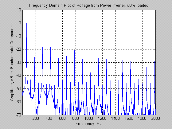
In comparing this plot to Figure 2, it is obvious that many more harmonic components are present in the signal (as we expected based on Figure 3). To keep comparison easy, this plot uses the same axis limits as in Figure 2. As before, we see the main line at 60 Hz (this was measured to also be right on the money). We also see that the even harmonic components are still quite small (as expected), and that the dominant harmonic components are odd (180 Hz, 300 Hz, 420 Hz, etc.). However, unlike the signal of Figure 2, the level of the odd harmonic components does not drop off nearly as fast. There are at least 12 harmonic lines exceeding the -30 dB level, whereas only one line exceeded this level in the standard household AC waveform. Now consider Figure 5 below:
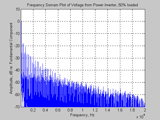
Figure 5 above is basically the same as Figure 4 except that Figure 5's horizontal axis extends to 20 kHz. As can be seen, there is significant energy above the -40 dB level out to about 5000 Hz. In the case of the standard household AC waveform, the -40 dB level of energy ended at about 400 Hz. This basically means that the inverter power waveform will contain significantly more power at the higher frequencies. In Figure 4, the 5th and 7th harmonics are each at a level of about -18 dB relative to the fundamental. In terms of voltage, this means that each of these components has a voltage level of about 12% that of the fundamental. In terms of power, these two harmonics (combined) have about 3.2% the power of the fundamental. I did a quick analysis of the total power in the harmonics of this signal: the result is about 9%. This means that of the 100 watts being output, about 91 watts was in the fundamental at 60 Hz, and the other 9 watts was at higher frequencies. More than likely, the design criteria used for this inverter was to keep 90% of the power in the fundamental. The designer probably figured this was suitable for a consumer device.
Discussion: After seeing how awful the AC voltage of the Inverter looks, many people may never want to use an AC inverter again! However, things are not as bad as they might initially seem. A lot depends on what the inverter is being used for. Certain items could care less about the quality of the power: such items include incandescent light bulbs and heating devices (however it is not generally a good idea to run heating devices from AC Inverters as the power requirements can be very high). As far as electronics items are concerned, in my opinion risk of "damage" to the device is probably small, however the comparatively large amount of high frequency energy present in the AC waveform may cause interference or other undesirable effects. For example, if powering an audio system or recording equipment, it is possible that the high frequency energy could couple into the system and be heard as a "buzzing" sound through the speakers. Items that are marginally designed may not like running on an inverter such as the one characterized by this article. Many electronic devices use transformers to convert 115 VAC to a lower internal working voltage. Power transformer cores are designed to work primarily with 60 Hz power. Application of higher frequencies can result in various losses in the core (eddy current losses for example) if the transformer is not specifically designed to operate with wideband signals. This in turn will cause the transformer to get hotter than normal. In my opinion a transformer would have to be of rather poor quality to not be able to satisfactorily operate on the waveforms seen in the inverter above. In most devices, the power supply is the stage that will have to immediately deal with the incoming AC power. Most well designed power supplies have very good filtering, so the DC voltage that is ultimately used to power internal circuits is usually quite immune to "dirty" power. Items that are very sensitive to DC power quality may be impacted if the power is excessively rich in high frequency energy however.
Conclusions: Based on the analysis performed above, the following conclusions can be made about the Radio Shack (Cat No. 22-138) AC Inverter:
The best advice is this: if you are concerned about potential damage to an expensive piece of equipment, it is recommended that you determine the characteristics of the AC power generated by the inverter before operating the device in question.
End of page... come back soon... Aloha!